Gate ~ FMCU ~ Benutzerhandbuch/en: Unterschied zwischen den Versionen
← Gate ~ FMCU ~ Benutzerhandbuch/en
(→Closing run at reduced speed) (Markierung: 2017-Quelltext-Bearbeitung) |
Inhaltsverzeichnis
Introduction[Bearbeiten | Quelltext bearbeiten]
The document describes the functions and configuration options of the software Facility Management Control Unit.
The Facility Management Control Unit is software for access control management. It can be used in an enclosed area such as a sports or entertainment center, an airport zone, universities or security areas. The main components of the software solution are:
- An automated passage control with two-part door and signal lighting
- Barcode (or/and RFID) scanners that read identification data from the customer's ticket or card
- Tracking cameras observing the passage of customers
- Info screens showing inbound and outbound information to the customer
- One or more external speakers
- One or more additional monitors with content tailored to customer needs
The main features are:
- Opening access control upon successful ticket validation
-
Interaction with customer in response to various events through:
- Light effects
- Voice prompts through internal or external speakers
- Acoustic confirmation of the reading process from barcode scanners
- Visual content displayed on an info screen
- Safe opening and closing of the swing doors by monitoring the passage area
Supported operating modes:
- Normal
- Service
- Fire alarm
- Emergency
The variants of Entry Tickets:
- Single entry ticket with closing of access control after passage of one person
- Multiple entry ticket with permanent access control
- Adjustable time intervals
- Consideration of additional conditions about potential-free contacts
Technical Information[Bearbeiten | Quelltext bearbeiten]
Configuration[Bearbeiten | Quelltext bearbeiten]
Step 1
After the software has been downloaded and transferred to the eMMC card according to the documented procedure, see also here Galaxy Gate Inbetriebnahme, the login screen appears after the first start. After logging in with the user Installer, the wizard with the definition of the IP configuration is started. 
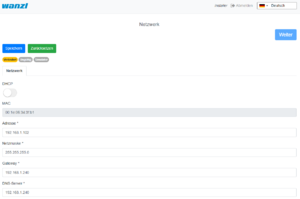
| Parameter | Description | Default Value |
|---|---|---|
| Address | IP-Address of access control | 192.168.1.100 |
| Mask | Network-Mask | 255.255.255.0 |
| Gateway | Gateway-Address | 192.168.1.1 |
| DNS-Server | DNS-Server for name resolution | 192.168.1.1 |
As a type, you can basically make this selection in the assistant.
| Selection | Description |
|---|---|
| No Device Slave | Slave Unit (Default Selection) |
| Galaxy Gate (Modbus Serial) | Master-Unit mit serieller Verbindung zu Slave-Unit |
| Galaxy Gate (Modbus TCP) | Master-Unit with network connection to Slave-Unit |
| Galaxy Port (Modbus Serial) | Unit with serial connection to Slave-Unit |
| Galaxy Port (Modbus TCP) | Unit with network connection to Slave-Unit |
| Function | Description |
|---|---|
| AEA | Configuration for Boarding Gates |
| Immediate Closure | Closing the swivel arms without swivel range monitoring |
| Multiple Opening | Swivel arms remain open when multiple input signals are present |
| Personal Protection | Closing the swivel arms with swivel area monitoring |
| One-time opening | Single pass even when several input signals are present |
| Trolley Case | Support of trolley case without alarm |
| Wheelchair | Assistance from wheelchair without alarm |
| Configuration Type | Description |
|---|---|
| AEA | Configuration for Boarding Gates |
| One-time opening Personal Protection | Closing the swivel arms with swivel area monitoring |
| One-time opening Immediate Closure | Closing the swivel arms without swivel range monitoring |
| One-time opening Trolley Case | Single passage with trolley case even when several input signals are present |
| One-time opening Wheelchair | Single passage with a wheelchair even if several input signals are present |
| Multiple opening personal protection | Closing the swivel arms with swivel area monitoring |
| Multiple opening instant closure | Closing the swivel arms with swivel area monitoring |
| Multi-opening trolley case | Swivel arms remain open when several people with wheeled suitcases pass through |
| Multiple opening wheelchair | Swivel arms remain open when several people with wheeled suitcases pass through |
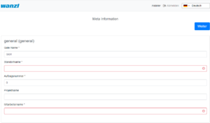
After the input fields have been filled in, you can click on Next to reach the next page of the wizard.
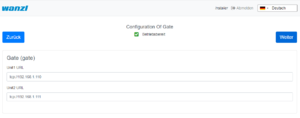
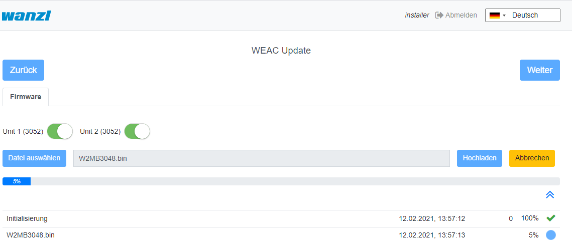
The current WEAC firmware is displayed on the next page of the wizard. If necessary, you can down or upgrade the firmware.
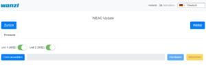
The firmware version for each unit is listed as a label next to the activation button. The navigation options are deactivated during the update process. The update process takes about 3 minutes for both units.
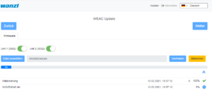
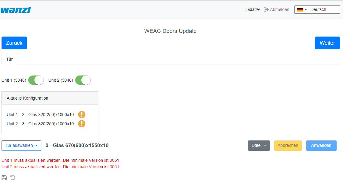
After checking the WEAC firmware, the swing doors are configured. It is automatically checked whether the minimum requirements regarding the firmware are met. You will be informed on the surface if the firmware has to be updated first.
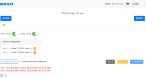
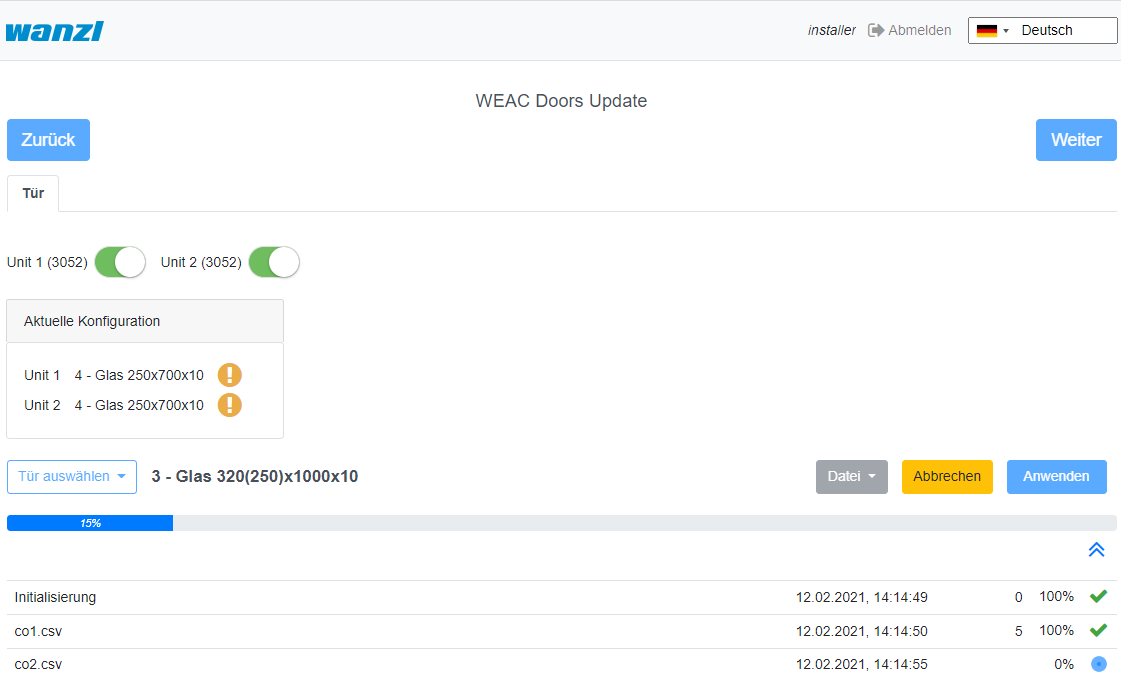
If the requirements are met, you can select the swing doors and apply them to the gate.
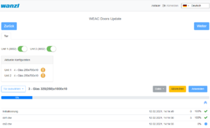
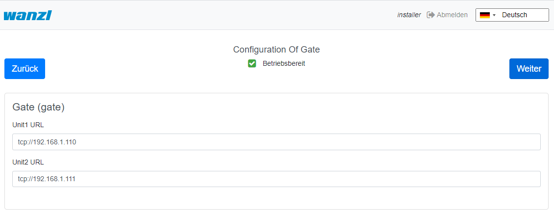
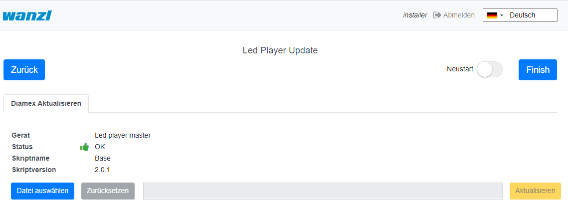
The next step is to configure the LED player for both units (Master and Slave) accomplished. If necessary, you can adjust the parameters. If the status is ready for use, no modifications are necessary.
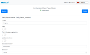
The current firmware of the LED player is shown again on the last page of the assistant. Optionally, you can end the configuration with a restart. However, this is only necessary if IP addresses or interface information have changed.
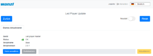
After clicking Finish, you can now log in again with a known credentials and work with the Galaxy Gate. If you log in again with the user installer, you get a graphical overview, can find out about the status of the access control and can carry out updates if necessary. This completes the setup of the access control.
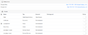
You can now log in with a service account and carry out further tests.
Operation Manual[Bearbeiten | Quelltext bearbeiten]
Configuration of the Swing Doors[Bearbeiten | Quelltext bearbeiten]
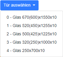
The swing doors can have different dimensions. Depending on the width and height, this results in other target parameters for optimal curve passage.
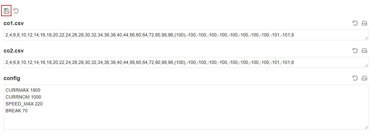
After a type has been selected, all parameters can be adjusted according to the needs in the interface before they are then activated via the button Apply in the configuration on the access control. If you change individual values in the display, the settings must first be saved. To do this, click on the diskette symbol on the left of the interface above the file list.
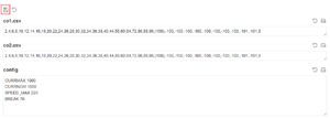
After the changes have been saved, you can activate them using the Apply button.
Configuration of the XOVIS Sensors[Bearbeiten | Quelltext bearbeiten]
Add XOVIS-Sensor
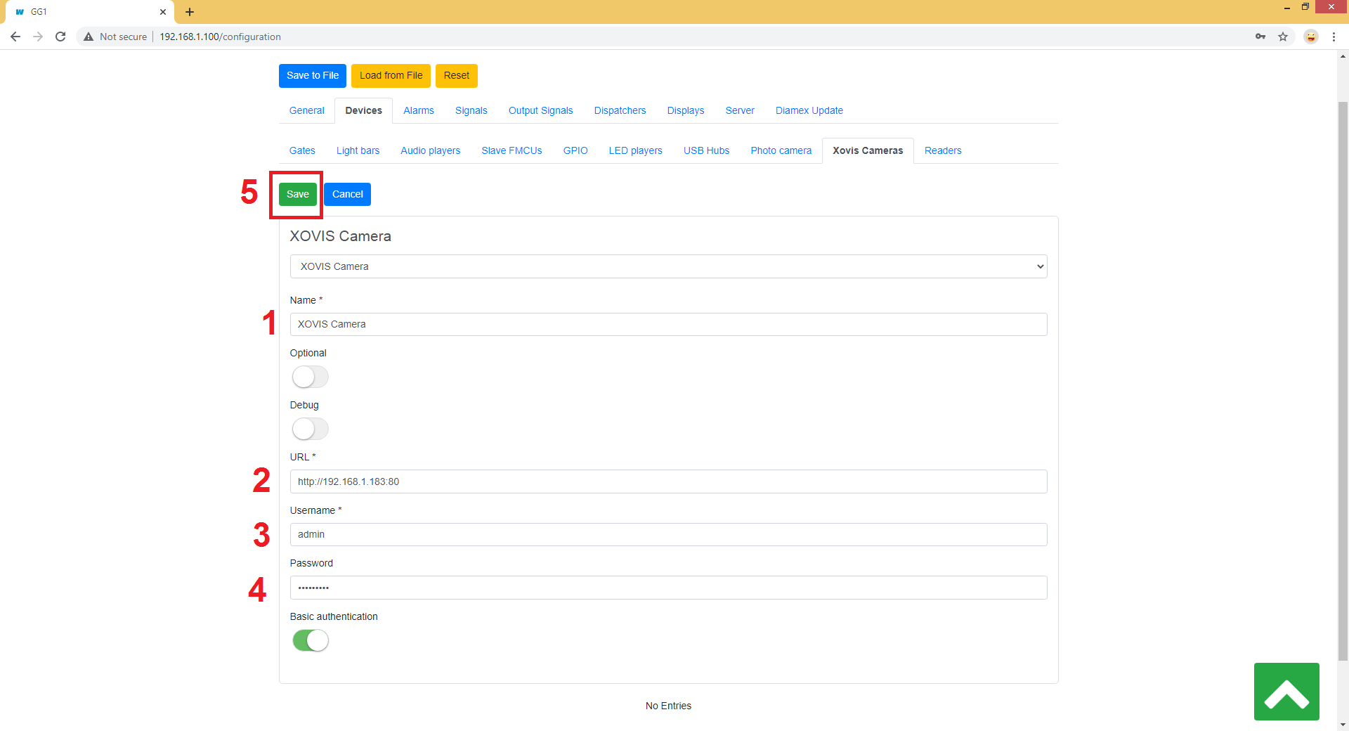
Navigate to "Configuration" -> "Devices" -> "Xovis Cameras" and then click on the "Add" button

The following fields are filled in the order shown:
- Name
- URL
- Username
- Password
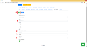 The configuration is saved by clicking the Save button.
Add XOVIS monitoring area as alarm signal
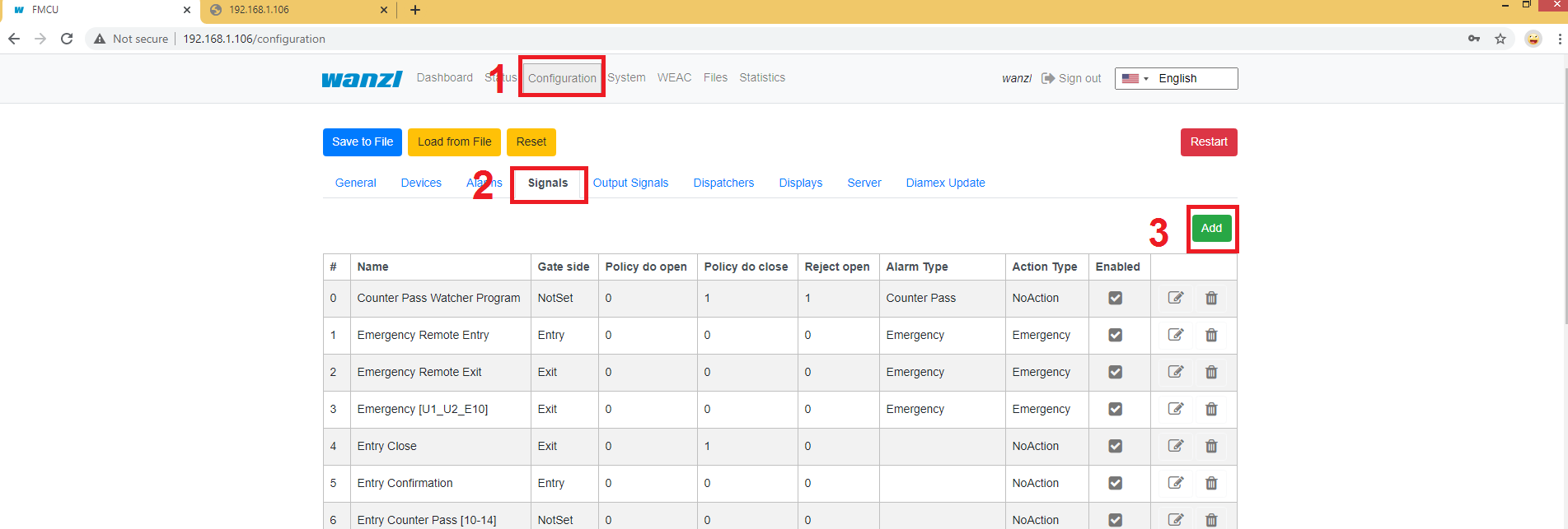
Navigate to "Configuration" -> "Signals" and then click on the "Add" button
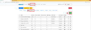
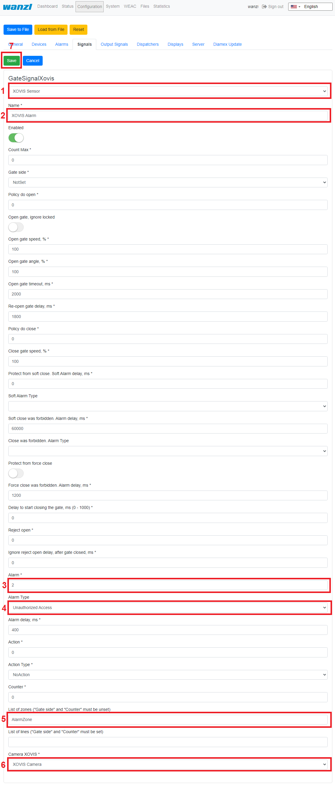
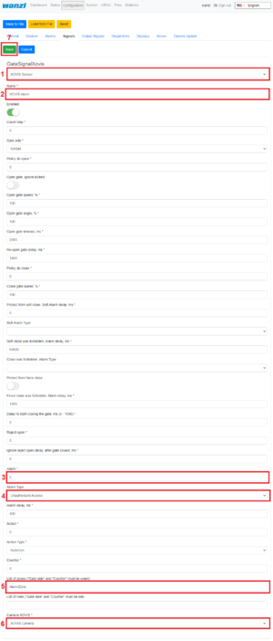
The following fields must be filled in here:
- Select type "XOVIS Sensor"
- Specify the name of the signal (e.g. "XOVIS ALARM")
- Set the minimum number of people in the alarm zone to trigger an alarm (e.g. 2)
- Select the alert type (e.g. "Unauthorized Access")
- Determine a list of alarm zones (e.g. "AlarmZone")
- Select the XOVIS sensor added to.
The configuration is saved by clicking the Save button.
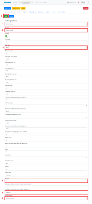
Add XOVIS counter
Navigate to "Configuration" -> "Signals" and then click on the "Add" button

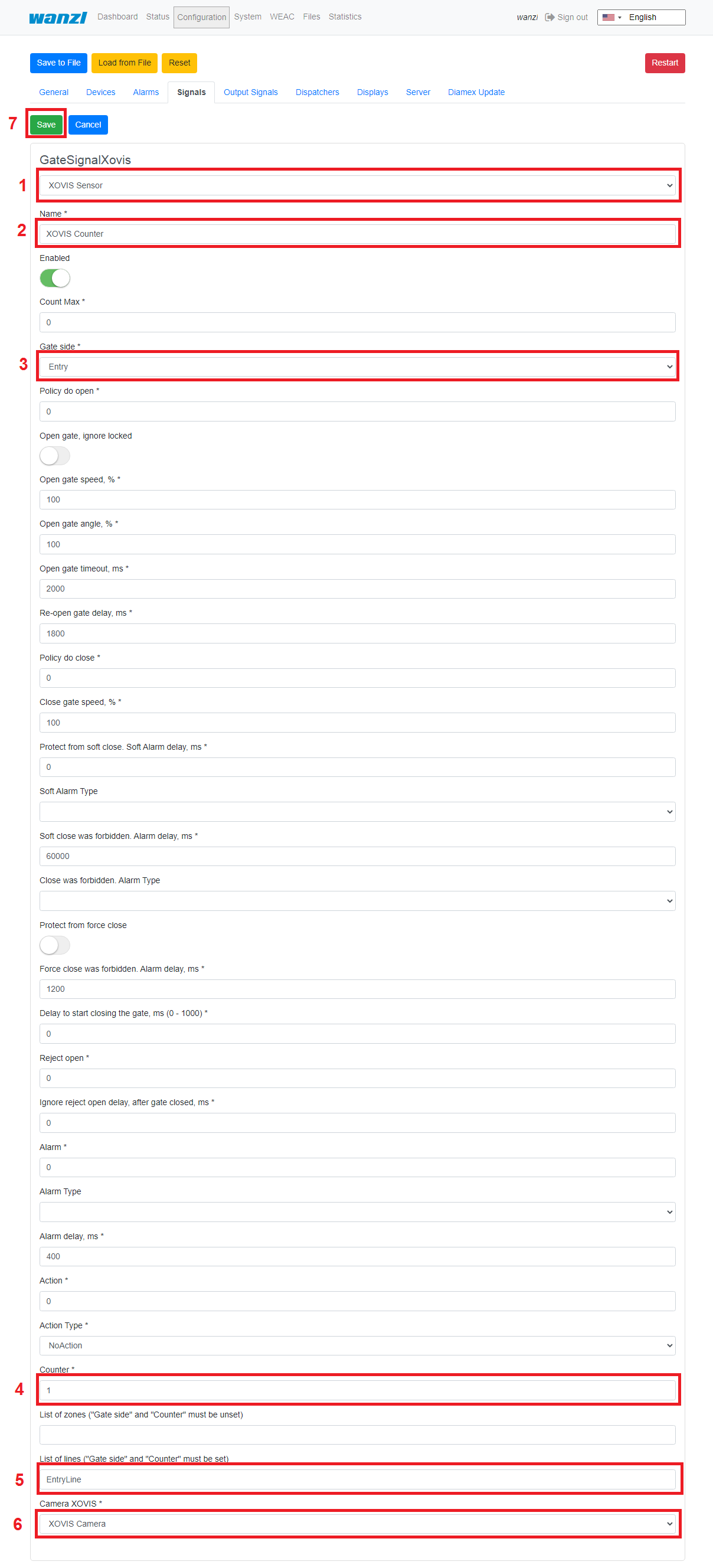
The following fields must be filled in here:
- Select type "XOVIS Sensor".
- Specify the name of the signal (e.g. "XOVIS Counter")
- Specify the side of the gate (e.g. "Entrance")
- Set the value "Counter".
- Specify a list of lines(e.g. "EntryLine")
- Select the XOVIS camera that you added earlier.
The configuration is saved by clicking the Save button.
Store VPN key[Bearbeiten | Quelltext bearbeiten]
A VPN key is required to use remote maintenance. This key can be requested from maxcrc support (support@maxcrc.de) by specifying the project name (Configuration->General view).
After the key file (*.opvn.conf) is available, you can import via the System->OpenVPN page. The following steps are necessary for this.
Navigating to the System-OpenVPN page.


This file is now specified via the Select file button in the file selection dialog. Then click on Upload. When the process has been successfully completed, an info icon will appear next to the start button. This means the file has been uploaded successfully, the OpenVPN client can now be activated by clicking on Start.

If the start was successful, the color changes from green to red and the label from start to stop. The status of the OpenVPN client and the IP address for access in the VPN network for this gate are displayed to the right of the info symbol. You can disable remote access by clicking the Stop button.
Softwareupdates[Bearbeiten | Quelltext bearbeiten]
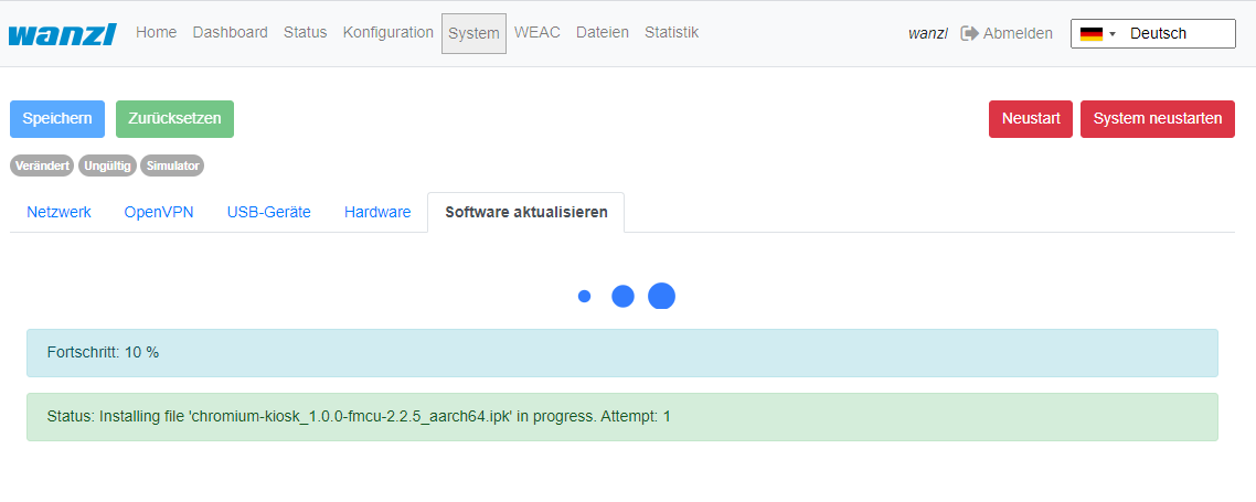
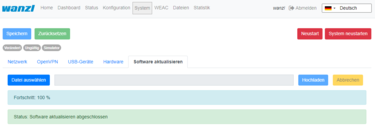
Display during installationIf there is no Internet connection, individual package installations can be carried out in the System->Update software menu. To do this, you create a zip archive with the packages to be installed beforehand. It must be ensured that no relative paths are used in the archive. Then you can insert the archive into the input line via Select file and start the update procedure with Upload. The progress process is displayed in the interface.
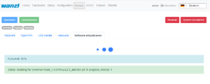 Anzeige nach Abschluss der Installation
If necessary, the application can be restarted.
Customer Role[Bearbeiten | Quelltext bearbeiten]
When you log in with the user client, a simplified interface appears with only three configuration menus "Home", "Status", "Statistics". 
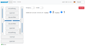
In this view you can administrate the access control, but you cannot make any configuration adjustments. The current statistics are displayed directly on the interface, a complete overview of the accesses can be viewed in the Statistics tab and exported if required. The current status of the individual access control components can be viewed in the Status tab. The Cleaning option disables all alarms to make the cleaning staff's job easier. The Emergency open option supports the user in opening the access control immediately.
Standard Assignment Connection Board[Bearbeiten | Quelltext bearbeiten]
Unit 1
| Port | Function | Description |
|---|---|---|
| LSU (E1) | LS Middle
Center Light barrier |
NO
Normally Open Contact |
| LSV (E2) | LS Entry
Photocell Input |
NO
normally open contact |
| E3 | Open Entry
Single free entry direction Impuls 0,1-1,0 Sek. |
NO
Normally Open Contact |
| E4 | Open Exit
Single free exit direction Impuls 0,1-1,0 Sek. |
NO
normally open contact |
| LSH (E5) | NA
not connected |
|
| E6 | State bit 0
Status bit 0 |
NO
normally open contact |
| E7 | State bit 1
Status bit 1 |
NO
normally open contact |
| E8 | Fire Alarm
fire alarm system (BMA) |
NC
normally closed contact |
| E9 | Open Entry 70%
Einzelfrei 70% Input Direction Impuls 0,1-1,0 Sek. |
NO
normally open contact |
| E10 | Emergency Open Button
emergency button |
NC
normally closed contact |
| A8 | Entry Confirmation
Confirmation of passage entry direction Impuls 0,5 Sek. |
+12 VDC |
| A9 | Exit Confirmation
Confirmation of passage exit direction Impuls 0,5 Sek. |
+12 VDC |
| Port | Function | Description |
|---|---|---|
| LSU (E1) | NA
not connected |
|
| LSV (E2) | NA
not connected |
|
| E3 | Open Entry
Single free entry direction Impuls 0,1-1,0 Sek. |
NO
normally open contact |
| E4 | Open Exit
Single free exit direction Impuls 0,1-1,0 Sek. |
NO
normally open contact |
| LSH (E5) | LS Exit
Photocell exit |
NO
normally open contact |
| E6 | State bit 2
Status bit 2 |
NO
normally open contact |
| E7 | State bit 3
status bit 3 |
NO
normally open contact |
| E8 | Fire Alarm
fire alarm system (BMA) |
NC
normally closed contact |
| E9 | Open Exit 70%
single free 70% exit direction Impuls 0,1-1,0 Sek. |
NO
normally open contact |
| E10 | Emergency Open Button
emergency button |
NC
normally closed contact |
| A8 | Alarm Impuls
Alarm Impuls 0,5 Sek. |
+12 VDC |
| A9 | Gate State Error
error condition Durchgang |
+12 VDC |
| Status | Unit 1 E6
Bit 0 |
Unit 1 E7
Bit 1 |
Unit 2 E6
Bit 2 |
Unit 2 E7
Bit 3 |
|---|---|---|---|---|
| Normal
Normal |
0 | 0 | 0 | 0 |
| Free Entry
Entrance permanently free |
1 | 0 | 0 | 0 |
| Lock Entry
entrance blocked |
0 | 1 | 0 | 0 |
| Service Entry
Permanently open entry direction |
1 | 1 | 0 | 0 |
| Free Exit
Exit permanently free |
0 | 0 | 1 | 0 |
| Free Entry/Exit
Input/Output permanently free(Not implemented) |
1 | 0 | 1 | 0 |
| Lock Entry / Free Exit
Entrance blocked / exit permanently free |
0 | 1 | 1 | 0 |
| tbd | 1 | 1 | 1 | 0 |
| Lock Exit
exit blocked |
0 | 0 | 0 | 1 |
| Free Entry / Lock Exit
Entrance permanently free / exit blocked |
1 | 0 | 0 | 1 |
| Lock
Gesperrt |
0 | 1 | 0 | 1 |
| tbd | 1 | 1 | 0 | 1 |
| Service Exit
Permanently open exit direction |
0 | 0 | 1 | 1 |
| tbd | 1 | 0 | 1 | 1 |
| tbd | 0 | 1 | 1 | 1 |
| Self Test
self test |
1 | 1 | 1 | 1 |
Alarmdefinition[Bearbeiten | Quelltext bearbeiten]
An alarm is triggered as a follow-up action from signals or other sources (e.g. devices). An alarm exists has several general characteristics. This includes a name, the definition of an action...
| Definition | Description | Status |
|---|---|---|
| Connection Alive | monitors connection to external application | on/off |
| Connection Lost | monitors connection to external application | on/off |
| Counter Pass | is set by anti-rotation protection is activated | on/off |
| Door Break-In | Door is forcibly moved when closed | on/off |
| Emergency | is set if the signals on unit 1 E8 or unit 2 E8 are not active (opener). | on/off |
| Fire Alarm | is set if the signals on unit 1 E10 or unit 2 E10 are not active (opener). | on/off |
| Invalid Ticket | is set if ticket validation fails | Impuls |
| Motionless Object | is set when an object is in the gate area for more than a defined period of time and closing is prevented by a timeout. | on/off |
| No Alarm | is set if no alarm is defined for signals | on/off |
| Proceed Alarm | analogous to Motionless Object with a different time span and other actions without light indication | on/off |
| Server Alarm | is triggered in the FMCU server | on/off |
| Tailgating | is set if more than one person is in the gate area | on/off |
| Unauthorized Access | is set if a person is in the gate area when the gate is closed | on/off |
| Valid Ticket | is set if the ticket validation was successful (trigger beep) | Impuls |
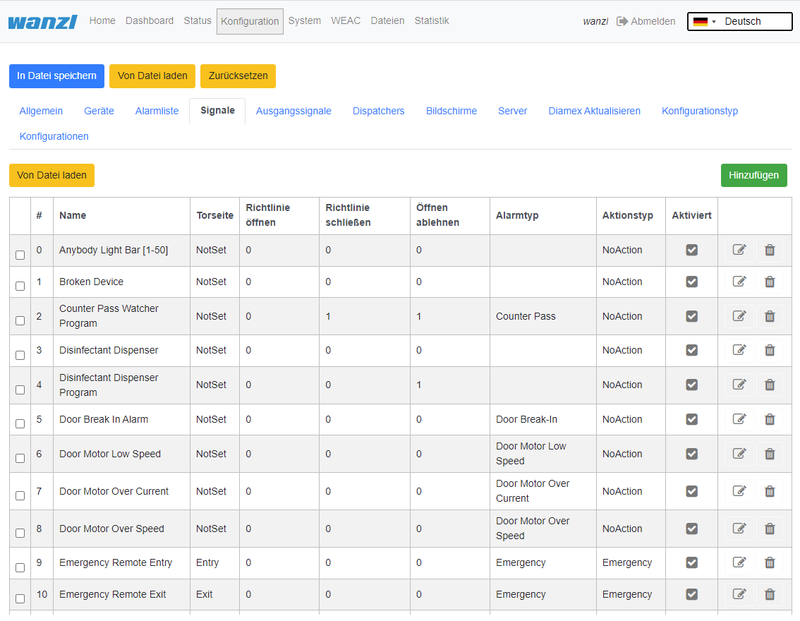
Signals[Bearbeiten | Quelltext bearbeiten]
The information in this section is based on FMCU software v2.3.7 and WEAC version 32.14.
Technical Background[Bearbeiten | Quelltext bearbeiten]
The FMCU software is based on a customized UNIX operating system, which has been produced using the Yocto Project. Only the required services are activated in the operating system. The optimal support packages for the CPU type are taken into account when creating the operating system. These so-called Board Support Packages (BSP) are provided by the hardware manufacturers and allow optimal and efficient utilization of the hardware resources.
Functions[Bearbeiten | Quelltext bearbeiten]
In principle, the functions are mapped via the signal processing. The signals are generated by different sources including:
- Light bar
- Light sensor
- Ceiling sensor
- Other
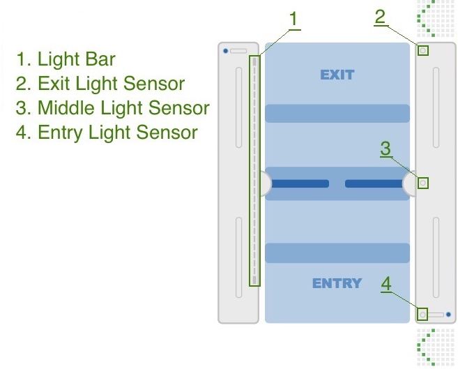
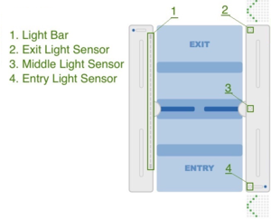
The location of the sensors is shown in the figure below. In each half of the frame there is a so-called "inner zone" and an "outer zone". When passing through an access control, a signal flow diagram is generated, which is used to map the following functions.
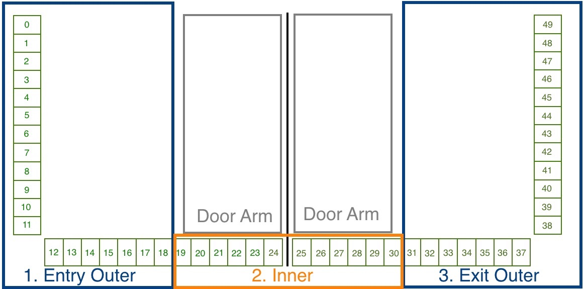
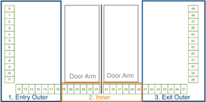
The light bar serves as a source for several signals and is also divided into different areas.
The following signals are installed in the standard configuration.
| Signal Name | Frame Half |
|---|---|
| Entry Confirmation | Entry |
| Entry Gate Sensor [U1_E2] | Entry |
| Entry Outer LightBar | Entry |
| Exit Inner LightBar | Entry |
| Free Entry [1000] | Entry |
| Lock Entry [0100] | Entry |
| Open Entry [U1_U2_E3] | Entry |
| Open Entry 70% [U1_E9] | Entry |
| Remote Open Entry | Entry |
| Service Entry [1100] | Entry |
| Emergency Remote | Exit |
| Emergency [U1_U2_E8] | Exit |
| Entry Inner LightBar | Exit |
| Exit Confirmation | Exit |
| Exit Gate Sensor [U2_E5] | Exit |
| Exit Outer LightBar | Exit |
| Free Exit [0010] | Exit |
| Lock Exit [0001] | Exit |
| Open Exit [U1_U2_E4] | Exit |
| Open Exit 70% [U2_E9] | Exit |
| Remote Open Exit | Exit |
| Service Exit [0011] | Exit |
Closing-run at reduced Speed[Bearbeiten | Quelltext bearbeiten]
This function applies to signals that have the property CloseGate > 0. For the affected signals, the value Close gate speed, % * must be defined with a value between 10 and 100%. It is therefore possible to define appropriate closing speeds for different passage scenarios. The default value is set to 100%. In the standard configuration, the following signals meet this requirement.
| Signal | Parameter | Value |
|---|---|---|
| Tailgating watcher | Close gate speed, % * | 100% |
| Entry Gate Sensor [U1_E2] | Close gate speed, % * | 100% |
| Exit Gate Sensor [U2_E5] | Close gate speed, % * | 100% |
| Entry Outer LightBar | Close gate speed, % * | 100% |
| Exit Outer LightBar Exit | Close gate speed, % * | 100% |
Passage Confirmation[Bearbeiten | Quelltext bearbeiten]
This function sets an impulse with an adjustable duration in the connection board for connection A8.
Suitcase Trolley Detection[Bearbeiten | Quelltext bearbeiten]
This function is active when the listed parameters are set for the following signals. It means that a person with a suitcase being pulled behind them can pass through prematurely closing swing doors without being disturbed.
| Signal | Parameter | Value |
|---|---|---|
| Middle Gate Sensor [U1_E1] | Protect from force close | true |
| Inner LightBar | Protect from force close | true |
Multiple Opening[Bearbeiten | Quelltext bearbeiten]
This function is only valid if a reader has been set up for the entry direction. It means that several people can pass through the entrance in a row without the swing door being closed in the meantime. Each person must present a ticket at the card reader at the entrance. The swing doors only remain open if the validation is successful. This function is active when the listed parameters are set for the following signals.
| Signal | Parameter | Value |
|---|---|---|
| Middle Gate Sensor [U1_E1] | Protect from force close | true |
| Inner LightBar | Protect from force close | true |
| Entry Outer LightBar | Protect from force close | true |
| Entry Gate Sensor [U1_E2] | Protect from force close | true |
| Tailgating watcher | Activated | false |
Tips for Working[Bearbeiten | Quelltext bearbeiten]
If you have lost the overview when configuring the signals, you can use the functionReset to Default
restore a defined initial state.Verwandte Themen
{{translate|Gate ~ FMCU Galaxy Gate ~ User Guide}}
{{DISPLAYTITLE:Gate ~ FMCU Galaxy Gate ~ User Guide}}
==Introduction==
The document describes the functions and configuration options of the software '''F'''acility '''M'''anagement '''C'''ontrol '''U'''nit.
The Facility Management Control Unit is software for access control management. It can be used in an enclosed area such as a sports or entertainment center, an airport zone, universities or security areas. The main components of the software solution are:
*An automated passage control with two-part door and signal lighting
*Barcode (or/and RFID) scanners that read identification data from the customer's ticket or card
*Tracking cameras observing the passage of customers
*Info screens showing inbound and outbound information to the customer
*One or more external speakers
*One or more additional monitors with content tailored to customer needs
The main features are:
*Opening access control upon successful ticket validation
*Interaction with customer in response to various events through:
**Light effects
**Voice prompts through internal or external speakers
**Acoustic confirmation of the reading process from barcode scanners
**Visual content displayed on an info screen
**Safe opening and closing of the swing doors by monitoring the passage area
Supported operating modes:
*Normal
*Service
*Fire alarm
*Emergency
The variants of Entry Tickets:
*Single entry ticket with closing of access control after passage of one person
*Multiple entry ticket with permanent access control
*Adjustable time intervals
*Consideration of additional conditions about potential-free contacts
==Technical Information==
===Configuration===
'''Step 1'''
After the software has been downloaded and transferred to the eMMC card according to the documented procedure, see also here [[Gate ~ FMCU ~ Inbetriebnahme|Galaxy Gate Inbetriebnahme]], the login screen appears after the first start. After logging in with the user ''Installer'', the wizard with the definition of the IP configuration is started.
[[Datei:image _network _assistant.png|mini|ohne]]
{| class="wikitable"
|+
!Parameter
!Description
!Default Value
|-
|Address
|IP-Address of access control
|192.168.1.100
|-
|Mask
|Network-Mask
|255.255.255.0
|-
|Gateway
|Gateway-Address
|192.168.1.1
|-
|DNS-Server
|DNS-Server for name resolution
|192.168.1.1
|}{{Box_Note|Note Text = The configuration always starts with the "Slave" side of the Galaxy Gate. This selection is preset in the assistant "No Device Slave".}}As a type, you can basically make this selection in the assistant.
{| class="wikitable"
|+Configuration of the Facility Management Control Unit
!Selection
!Description
|-
|No Device Slave
|Slave Unit (Default Selection)
|-
|Galaxy Gate (Modbus Serial)
|Master-Unit mit serieller Verbindung zu Slave-Unit
|-
|Galaxy Gate (Modbus TCP)
|Master-Unit with network connection to Slave-Unit
|-
|Galaxy Port (Modbus Serial)
|Unit with serial connection to Slave-Unit
|-
|Galaxy Port (Modbus TCP)
|Unit with network connection to Slave-Unit
|}
{| class="wikitable"
|+Functions
!Function
!Description
|-
|AEA
|Configuration for Boarding Gates
|-
|Immediate Closure
|Closing the swivel arms without swivel range monitoring
|-
|Multiple Opening
|Swivel arms remain open when multiple input signals are present
|-
|Personal Protection
|Closing the swivel arms with swivel area monitoring
|-
|One-time opening
|Single pass even when several input signals are present
|-
|Trolley Case
|Support of trolley case without alarm
|-
|Wheelchair
|Assistance from wheelchair without alarm
|}After the function has been selected, the combination of functions results in corresponding configuration types. The function selection is a filter for the resulting configuration type.
{| class="wikitable"
|+Configuration type from combination of functions
!Configuration Type
!Description
|-
|AEA
|Configuration for Boarding Gates
|-
|One-time opening Personal Protection
|Closing the swivel arms with swivel area monitoring
|-
|One-time opening Immediate Closure
|Closing the swivel arms without swivel range monitoring
|-
|One-time opening Trolley Case
|Single passage with trolley case even when several input signals are present
|-
|One-time opening Wheelchair
|Single passage with a wheelchair even if several input signals are present
|-
|Multiple opening personal protection
|Closing the swivel arms with swivel area monitoring
|-
|Multiple opening instant closure
|Closing the swivel arms with swivel area monitoring
|-
|Multi-opening trolley case
|Swivel arms remain open when several people with wheeled suitcases pass through
|-
|Multiple opening wheelchair
|Swivel arms remain open when several people with wheeled suitcases pass through
|}After choosing from the three lists, click on '''Apply''', the application will be restarted, you have to wait for the start-up process to be completed. After logging in again, this screen appears.{{Box_Note|Note Text = If you adjust the IP address in the configuration, you must also align the URL in the browser to the new IP address.}}[[Datei:image _assistant _step02.png|ohne|mini]]]]
After the input fields have been filled in, you can click on '''Next''' to reach the next page of the wizard.
[[Datei:image _assistant _step03.png|ohne|mini]]]]
The current WEAC firmware is displayed on the next page of the wizard. If necessary, you can down or upgrade the firmware.
[[Datei:image _assistant _step04.png|ohne|mini]]]]
The firmware version for each unit is listed as a label next to the activation button. The navigation options are deactivated during the update process. The update process takes about 3 minutes for both units.
[[Datei:image _assistant _04a.png|ohne|mini]]]]
After checking the WEAC firmware, the swing doors are configured. It is automatically checked whether the minimum requirements regarding the firmware are met. You will be informed on the surface if the firmware has to be updated first.
[[Datei:image _assistant _05.png|ohne|mini]]]]
If the requirements are met, you can select the swing doors and apply them to the gate.
[[Datei:image _assistant _step06.png|ohne|mini]]]]
The next step is to configure the LED player for both units (Master and Slave) accomplished. If necessary, you can adjust the parameters. If the status is '''ready for use''', no modifications are necessary.
[[Datei:image _assistant _step07.png|ohne|mini]]]]
The current firmware of the LED player is shown again on the last page of the assistant. Optionally, you can end the configuration with a restart. However, this is only necessary if IP addresses or interface information have changed.
[[Datei:image _assistant _Step08.png|ohne|mini]]]]
After clicking '''Finish''', you can now log in again with a known credentials and work with the Galaxy Gate. If you log in again with the user installer, you get a graphical overview, can find out about the status of the access control and can carry out updates if necessary.
This completes the setup of the access control.
[[Datei:image _status.png|ohne|mini]]]]
You can now log in with a service account and carry out further tests.
==Operation Manual==
===Configuration of the Swing Doors===
The swing doors can have different dimensions. Depending on the width and height, this results in other target parameters for optimal curve passage.
[[Datei:image _glasdoors.png|ohne|mini]]]]
After a type has been selected, all parameters can be adjusted according to the needs in the interface before they are then activated via the button '''Apply''' in the configuration on the access control. If you change individual values in the display, the settings must first be saved. To do this, click on the diskette symbol on the left of the interface above the file list.
[[Datei:image _door _settings.png|ohne|mini]]]]
After the changes have been saved, you can activate them using the Apply button.
===Configuration of the XOVIS Sensors===
'''Add XOVIS-Sensor'''
Navigate to "Configuration" -> "Devices" -> "Xovis Cameras" and then click on the "Add" button
[[Datei:add _xovis _device _1.png|ohne|mini]]]]
The following fields are filled in the order shown:
#Name
#URL
#Username
#Password
[[Datei:add _xovis _device _2.png|ohne|mini]]]]
The configuration is saved by clicking the '''Save''' button.{{Box_Note|Note Text = After adding the XOVIS sensor, the '''FMCU''' must be restarted before proceeding with the configuration.}}'''Add XOVIS monitoring area as alarm signal'''
Navigate to "Configuration" -> "Signals" and then click on the "Add" button
[[Datei:add _xovis _alarm _signal _1.png|ohne|mini]]]]
The following fields must be filled in here:
#Select type "XOVIS Sensor"
#Specify the name of the signal (e.g. "XOVIS ALARM")
#Set the minimum number of people in the alarm zone to trigger an alarm (e.g. 2)
#Select the alert type (e.g. "Unauthorized Access")
#Determine a list of alarm zones (e.g. "AlarmZone")
#Select the XOVIS sensor added to.
The configuration is saved by clicking the '''Save''' button.
[[Datei:add _xovis _alarm _signal _2.png|mini|ohne]]]]
'''Add XOVIS counter'''
Navigate to "Configuration" -> "Signals" and then click on the "Add" button
[[Datei:add _xovis _alarm _signal _1.png|ohne|mini]]]]
The following fields must be filled in here:
#Select type "XOVIS Sensor".
#Specify the name of the signal (e.g. "XOVIS Counter")
#Specify the side of the gate (e.g. "Entrance")
#Set the value "Counter".
#Specify a list of lines(e.g. "EntryLine")
#Select the XOVIS camera that you added earlier.
The configuration is saved by clicking the '''Save''' button.
[[Datei:add _xovis _counter _signal.png|mini|ohne]]
===Store VPN key===
A VPN key is required to use remote maintenance. This key can be requested from maxcrc support (support@maxcrc.de) by specifying the project name (Configuration->General view).
After the key file (*.opvn.conf) is available, you can import via the System->OpenVPN page. The following steps are necessary for this.
Navigating to the '''System-OpenVPN''' page.
[[Datei:image _openvpn _step01.png|ohne|mini]][[Datei:image _openvpn _step02.png|mini]]]]
This file is now specified via the '''Select file''' button in the file selection dialog. Then click on '''Upload'''. When the process has been successfully completed, an info icon will appear next to the start button. This means the file has been uploaded successfully, the OpenVPN client can now be activated by clicking on '''Start'''.
[[Datei:image _openvpn _step03.png|ohne|mini]]]]
If the start was successful, the color changes from green to red and the label from start to stop. The status of the OpenVPN client and the IP address for access in the VPN network for this gate are displayed to the right of the info symbol. You can disable remote access by clicking the '''Stop''' button.
===Softwareupdates===
If there is no Internet connection, individual package installations can be carried out in the '''System->Update software''' menu. To do this, you create a zip archive with the packages to be installed beforehand. It must be ensured that no relative paths are used in the archive. Then you can insert the archive into the input line via '''Select file''' and start the update procedure with '''Upload'''. The progress process is displayed in the interface.
[[Datei:image _software _update.png|ohne|mini|Display during installation]][[Datei:image update 01.png|ohne|mini|375x375px|Anzeige nach Abschluss der Installation]]]][[Datei:image_update_01.png|375x375px]]
If necessary, the application can be restarted.
===Customer Role===
When you log in with the user client, a simplified interface appears with only three configuration menus "Home", "Status", "Statistics".
[[Datei:image _customer _view.png|ohne|mini]]]]
In this view you can administrate the access control, but you cannot make any configuration adjustments. The current statistics are displayed directly on the interface, a complete overview of the accesses can be viewed in the '''Statistics''' tab and exported if required. The current status of the individual access control components can be viewed in the '''Status''' tab. The '''Cleaning''' option disables all alarms to make the cleaning staff's job easier. The '''Emergency open''' option supports the user in opening the access control immediately.
===Standard Assignment Connection Board===
'''Unit 1'''
{| class="wikitable"
|+
!Port
!Function
!Description
|-
|'''LSU (E1)'''
|LS Middle
''Center Light barrier''
|NO
''Normally Open Contact''
|-
|'''LSV (E2)'''
|LS Entry
''Photocell Input''
|NO
''normally open contact''
|-
|'''E3'''
|Open Entry
''Single free entry direction Impuls 0,1-1,0 Sek.''
|NO
''Normally Open Contact''
|-
|'''E4'''
|Open Exit
''Single free exit direction Impuls 0,1-1,0 Sek.''
|NO
''normally open contact''
|-
|'''LSH (E5)'''
|NA
''not connected''
|
|-
|'''E6'''
|State bit 0
''Status bit 0''
|NO
''normally open contact''
|-
|'''E7'''
|State bit 1
''Status bit 1''
|NO
''normally open contact''
|-
|'''E8'''
|Fire Alarm
''fire alarm system (BMA)''
|NC
''normally closed contact''
|-
|'''E9'''
|Open Entry 70%
''Einzelfrei 70% Input Direction Impuls 0,1-1,0 Sek.''
|NO
''normally open contact''
|-
|'''E10'''
|Emergency Open Button
''emergency button''
|NC
''normally closed contact''
|-
|'''A8'''
|Entry Confirmation
''Confirmation of passage entry direction Impuls 0,5 Sek.''
| +12 VDC
|-
|'''A9'''
|Exit Confirmation
''Confirmation of passage exit direction Impuls 0,5 Sek.''
| +12 VDC
|}'''Unit 2'''
{| class="wikitable"
|+
!Port
!Function
!Description
|-
|'''LSU (E1)'''
|NA
''not connected''
|
|-
|'''LSV (E2)'''
|NA
''not connected''
|
|-
|'''E3'''
|Open Entry
''Single free entry direction Impuls 0,1-1,0 Sek.''
|NO
''normally open contact''
|-
|'''E4'''
|Open Exit
''Single free exit direction Impuls 0,1-1,0 Sek.''
|NO
''normally open contact''
|-
|'''LSH (E5)'''
|LS Exit
''Photocell exit''
|NO
''normally open contact''
|-
|'''E6'''
|State bit 2
''Status bit 2''
|NO
''normally open contact''
|-
|'''E7'''
|State bit 3
''status bit 3''
|NO
''normally open contact''
|-
|'''E8'''
|Fire Alarm
''fire alarm system (BMA)''
|NC
''normally closed contact''
|-
|'''E9'''
|Open Exit 70%
''single free 70% exit direction Impuls 0,1-1,0 Sek.''
|NO
''normally open contact''
|-
|'''E10'''
|Emergency Open Button
''emergency button''
|NC
''normally closed contact''
|-
|'''A8'''
|Alarm Impuls
''Alarm Impuls 0,5 Sek.''
| +12 VDC
|-
|'''A9'''
|Gate State Error
''error condition Durchgang''
| +12 VDC
|}'''Status Zustandsbits'''
{| class="wikitable"
|+
!Status
!Unit 1 E6
Bit 0
!Unit 1 E7
Bit 1
!Unit 2 E6
Bit 2
!Unit 2 E7
Bit 3
|-
|Normal
''Normal''
!'''0'''
!'''0'''
!'''0'''
!'''0'''
|-
|Free Entry
''Entrance permanently free''
!'''1'''
!'''0'''
!'''0'''
!'''0'''
|-
|Lock Entry
''entrance blocked''
!'''0'''
!'''1'''
!'''0'''
!'''0'''
|-
|Service Entry
''Permanently open entry direction''
!'''1'''
!'''1'''
!'''0'''
!'''0'''
|-
|Free Exit
''Exit permanently free''
!'''0'''
!'''0'''
!'''1'''
!'''0'''
|-
|Free Entry/Exit
''Input/Output permanently free('''Not implemented''')''
!'''1'''
!'''0'''
!'''1'''
!'''0'''
|-
|Lock Entry / Free Exit
''Entrance blocked / exit permanently free''
!'''0'''
!'''1'''
!'''1'''
!'''0'''
|-
|tbd
!'''1'''
!'''1'''
!'''1'''
!'''0'''
|-
|Lock Exit
''exit blocked''
!'''0'''
!'''0'''
!'''0'''
!'''1'''
|-
|Free Entry / Lock Exit
''Entrance permanently free / exit blocked''
!'''1'''
!'''0'''
!'''0'''
!'''1'''
|-
|Lock
''Gesperrt''
!'''0'''
!'''1'''
!'''0'''
!'''1'''
|-
|tbd
!'''1'''
!'''1'''
!'''0'''
!'''1'''
|-
|Service Exit
''Permanently open exit direction''
!'''0'''
!'''0'''
!'''1'''
!'''1'''
|-
|tbd
!'''1'''
!'''0'''
!'''1'''
!'''1'''
|-
|tbd
!'''0'''
!'''1'''
!'''1'''
!'''1'''
|-
|Self Test
''self test''
!'''1'''
!'''1'''
!'''1'''
!'''1'''
|}
===Alarmdefinition===
An alarm is triggered as a follow-up action from signals or other sources (e.g. devices). An alarm exists has several general characteristics. This includes a name, the definition of an action...
{| class="wikitable"
|+
!Definition
!Description
!Status
|-
|Connection Alive
|monitors connection to external application
|on/off
|-
|Connection Lost
|monitors connection to external application
|on/off
|-
|Counter Pass
|is set by anti-rotation protection is activated
|on/off
|-
|Door Break-In
|Door is forcibly moved when closed
|on/off
|-
|Emergency
|is set if the signals on unit 1 E8 or unit 2 E8 are not active (opener).
|on/off
|-
|Fire Alarm
|is set if the signals on unit 1 E10 or unit 2 E10 are not active (opener).
|on/off
|-
|Invalid Ticket
|is set if ticket validation fails
|Impuls
|-
|Motionless Object
|is set when an object is in the gate area for more than a defined period of time and closing is prevented by a timeout.
|on/off
|-
|No Alarm
|is set if no alarm is defined for signals
|on/off
|-
|Proceed Alarm
|analogous to Motionless Object with a different time span and other actions without light indication
|on/off
|-
|Server Alarm
|is triggered in the FMCU server
|on/off
|-
|Tailgating
|is set if more than one person is in the gate area
|on/off
|-
|Unauthorized Access
|is set if a person is in the gate area when the gate is closed
|on/off
|-
|Valid Ticket
|is set if the ticket validation was successful (trigger beep)
|Impuls
|}
===Signals===
The information in this section is based on FMCU software v2.3.7 and WEAC version 32.14.
[[Datei:FMCU-Signale.png|rahmenlos|800x621px]]
==Technical Background==
The '''FMCU''' software is based on a customized UNIX operating system, which has been produced using the [https://www.yoctoproject.org/ Yocto Project]. Only the required services are activated in the operating system. The optimal support packages for the CPU type are taken into account when creating the operating system. These so-called '''B'''oard '''S'''upport '''P'''ackages (BSP) are provided by the hardware manufacturers and allow optimal and efficient utilization of the hardware resources.
==Functions==
In principle, the functions are mapped via the signal processing. The signals are generated by different sources including:
*Light bar
*Light sensor
*Ceiling sensor
*Other
The location of the sensors is shown in the figure below. In each half of the frame there is a so-called "inner zone" and an "outer zone". When passing through an access control, a signal flow diagram is generated, which is used to map the following functions.
[[Datei:image _sensors.png|ohne|mini]]]]
The light bar serves as a source for several signals and is also divided into different areas.
[[Datei:image _lightbar.png|ohne|mini]]]]
The following signals are installed in the standard configuration.
{| class="wikitable"
|+
!Signal Name
!Frame Half
|-
|Entry Confirmation
|Entry
|-
|Entry Gate Sensor [U1_E2]
|Entry
|-
|Entry Outer LightBar
|Entry
|-
|Exit Inner LightBar
|Entry
|-
|Free Entry [1000]
|Entry
|-
|Lock Entry [0100]
|Entry
|-
|Open Entry [U1_U2_E3]
|Entry
|-
|Open Entry 70% [U1_E9]
|Entry
|-
|Remote Open Entry
|Entry
|-
|Service Entry [1100]
|Entry
|-
|Emergency Remote
|Exit
|-
|Emergency [U1_U2_E8]
|Exit
|-
|Entry Inner LightBar
|Exit
|-
|Exit Confirmation
|Exit
|-
|Exit Gate Sensor [U2_E5]
|Exit
|-
|Exit Outer LightBar
|Exit
|-
|Free Exit [0010]
|Exit
|-
|Lock Exit [0001]
|Exit
|-
|Open Exit [U1_U2_E4]
|Exit
|-
|Open Exit 70% [U2_E9]
|Exit
|-
|Remote Open Exit
|Exit
|-
|Service Exit [0011]
|Exit
|}
===Closing-run at reduced Speed===
This function applies to signals that have the property '''CloseGate > 0'''. For the affected signals, the value '''Close gate speed, % *''' must be defined with a value between 10 and 100%. It is therefore possible to define appropriate closing speeds for different passage scenarios. The default value is set to 100%. In the standard configuration, the following signals meet this requirement.
{| class="wikitable"
|+
!Signal
!Parameter
!Value
|-
|Tailgating watcher
|Close gate speed, % *
|100%
|-
|Entry Gate Sensor [U1_E2]
|Close gate speed, % *
|100%
|-
|Exit Gate Sensor [U2_E5]
|Close gate speed, % *
|100%
|-
|Entry Outer LightBar
|Close gate speed, % *
|100%
|-
|Exit Outer LightBar Exit
|Close gate speed, % *
|100%
|}
===Passage Confirmation===
This function sets an impulse with an adjustable duration in the connection board for connection '''A8'''.
===Suitcase Trolley Detection===
This function is active when the listed parameters are set for the following signals. It means that a person with a suitcase being pulled behind them can pass through prematurely closing swing doors without being disturbed.
{| class="wikitable"
|+
!Signal
!Parameter
!Value
|-
|Middle Gate Sensor [U1_E1]
|Protect from force close
|true
|-
|Inner LightBar
|Protect from force close
|true
|}
===Multiple Opening===
This function is only valid if a reader has been set up for the entry direction. It means that several people can pass through the entrance in a row without the swing door being closed in the meantime. Each person must present a ticket at the card reader at the entrance. The swing doors only remain open if the validation is successful. This function is active when the listed parameters are set for the following signals.
{| class="wikitable"
|+
!Signal
!Parameter
!Value
|-
|Middle Gate Sensor [U1_E1]
|Protect from force close
|true
|-
|Inner LightBar
|Protect from force close
|true
|-
|Entry Outer LightBar
|Protect from force close
|true
|-
|Entry Gate Sensor [U1_E2]
|Protect from force close
|true
|-
|Tailgating watcher
|Activated
|false
|}
==Tips for Working==
[[Datei:image reset-to default.png|rechts|rahmenlos]]If you have lost the overview when configuring the signals, you can use the function
'''Reset to Default'''
restore a defined initial state.{{Box_Note|Note Text = If you use the "Rest to Default" function, the current settings will be lost. If necessary, you can export the current configuration before this step.}}{{Links
|
| Thema1 = [[Gate_~_FMCU_Galaxy_Gate_~_user_manual | Galaxy Gate Bedienungsanleitung]]
| Thema2 = [[Gate_~_FMCU_~_management_dashboard | Beschreibung zentrales Dashboard]]
| Thema3 = [[Gate_~_FMCU_~_Inbetriebnahme | Galaxy Gate Inbetriebnahme]]
| Thema4 = [[Gate ~ FMCU ~ Installation Aquado PC (APP Server) | Applikationsserver Zutrittskontrollen]]
| Thema5 = [[Gate ~ FMCU ~ Checkliste | Zutrittskontrollen Checkliste IT Infrastruktur]]
|
}}
[[Kategorie:Galaxy Gate EN]]| Zeile 43: | Zeile 43: | ||
'''Step 1''' | '''Step 1''' | ||
| − | After the software has been downloaded and transferred to the eMMC card according to the documented procedure, see also here [[Gate ~ FMCU ~ Inbetriebnahme|Galaxy Gate Inbetriebnahme]], the login screen appears after the first start. After logging in with the user ''Installer'', the wizard with the definition of the IP configuration is started.[[Datei: | + | After the software has been downloaded and transferred to the eMMC card according to the documented procedure, see also here [[Gate ~ FMCU ~ Inbetriebnahme|Galaxy Gate Inbetriebnahme]], the login screen appears after the first start. After logging in with the user ''Installer'', the wizard with the definition of the IP configuration is started. |
| + | [[Datei:image_network_assistant.png]] | ||
{| class="wikitable" | {| class="wikitable" | ||
|+ | |+ | ||
| Zeile 143: | Zeile 144: | ||
|Multiple opening wheelchair | |Multiple opening wheelchair | ||
|Swivel arms remain open when several people with wheeled suitcases pass through | |Swivel arms remain open when several people with wheeled suitcases pass through | ||
| − | |}After choosing from the three lists, click on '''Apply''', the application will be restarted, you have to wait for the start-up process to be completed. After logging in again, this screen appears.{{Box_Note|Note Text = If you adjust the IP address in the configuration, you must also align the URL in the browser to the new IP address.}}[[Datei: | + | |}After choosing from the three lists, click on '''Apply''', the application will be restarted, you have to wait for the start-up process to be completed. After logging in again, this screen appears.{{Box_Note|Note Text = If you adjust the IP address in the configuration, you must also align the URL in the browser to the new IP address.}}[[Datei:image_assistant_step02.png]] |
| − | This completes the setup of the access control.[[Datei: | + | |
| + | After the input fields have been filled in, you can click on '''Next''' to reach the next page of the wizard. | ||
| + | |||
| + | [[Datei:image_assistant_step03.png]] | ||
| + | |||
| + | The current WEAC firmware is displayed on the next page of the wizard. If necessary, you can down or upgrade the firmware. | ||
| + | |||
| + | [[Datei:image_assistant_step04.png]] | ||
| + | |||
| + | The firmware version for each unit is listed as a label next to the activation button. The navigation options are deactivated during the update process. The update process takes about 3 minutes for both units. | ||
| + | |||
| + | [[Datei:image_assistant_04a.png]] | ||
| + | |||
| + | After checking the WEAC firmware, the swing doors are configured. It is automatically checked whether the minimum requirements regarding the firmware are met. You will be informed on the surface if the firmware has to be updated first. | ||
| + | |||
| + | [[Datei:image_assistant_05.png]] | ||
| + | |||
| + | If the requirements are met, you can select the swing doors and apply them to the gate. | ||
| + | |||
| + | [[Datei:image_assistant_step06.png]] | ||
| + | |||
| + | The next step is to configure the LED player for both units (Master and Slave) accomplished. If necessary, you can adjust the parameters. If the status is '''ready for use''', no modifications are necessary. | ||
| + | |||
| + | [[Datei:image_assistant_step07.png]] | ||
| + | |||
| + | The current firmware of the LED player is shown again on the last page of the assistant. Optionally, you can end the configuration with a restart. However, this is only necessary if IP addresses or interface information have changed. | ||
| + | |||
| + | [[Datei:image_assistant_Step08.png]] | ||
| + | |||
| + | After clicking '''Finish''', you can now log in again with a known credentials and work with the Galaxy Gate. If you log in again with the user installer, you get a graphical overview, can find out about the status of the access control and can carry out updates if necessary. | ||
| + | This completes the setup of the access control. | ||
| + | |||
| + | [[Datei:image_status.png]] | ||
| + | |||
| + | You can now log in with a service account and carry out further tests. | ||
==Operation Manual== | ==Operation Manual== | ||
===Configuration of the Swing Doors=== | ===Configuration of the Swing Doors=== | ||
| − | The swing doors can have different dimensions. Depending on the width and height, this results in other target parameters for optimal curve passage.[[Datei: | + | The swing doors can have different dimensions. Depending on the width and height, this results in other target parameters for optimal curve passage. |
| + | [[Datei:image_glasdoors.png]] | ||
| + | |||
| + | After a type has been selected, all parameters can be adjusted according to the needs in the interface before they are then activated via the button '''Apply''' in the configuration on the access control. If you change individual values in the display, the settings must first be saved. To do this, click on the diskette symbol on the left of the interface above the file list. | ||
| + | |||
| + | [[Datei:image_door_settings.png]] | ||
| + | |||
| + | After the changes have been saved, you can activate them using the Apply button. | ||
===Configuration of the XOVIS Sensors=== | ===Configuration of the XOVIS Sensors=== | ||
'''Add XOVIS-Sensor''' | '''Add XOVIS-Sensor''' | ||
| − | Navigate to "Configuration" -> "Devices" -> "Xovis Cameras" and then click on the "Add" button[[Datei: | + | Navigate to "Configuration" -> "Devices" -> "Xovis Cameras" and then click on the "Add" button |
| + | |||
| + | [[Datei:add_xovis_device_1.png]] | ||
| + | |||
| + | The following fields are filled in the order shown: | ||
#Name | #Name | ||
| Zeile 159: | Zeile 205: | ||
#Password | #Password | ||
| − | [[Datei: | + | [[Datei:add_xovis_device_2.png]] |
| + | |||
| + | The configuration is saved by clicking the '''Save''' button.{{Box_Note|Note Text = After adding the XOVIS sensor, the '''FMCU''' must be restarted before proceeding with the configuration.}}'''Add XOVIS monitoring area as alarm signal''' | ||
| + | |||
| + | Navigate to "Configuration" -> "Signals" and then click on the "Add" button | ||
| + | |||
| + | [[Datei:add_xovis_alarm_signal_1.png]] | ||
| − | + | The following fields must be filled in here: | |
#Select type "XOVIS Sensor" | #Select type "XOVIS Sensor" | ||
| Zeile 170: | Zeile 222: | ||
#Select the XOVIS sensor added to. | #Select the XOVIS sensor added to. | ||
| − | The configuration is saved by clicking the '''Save''' button.[[Datei: | + | The configuration is saved by clicking the '''Save''' button. |
| + | |||
| + | [[Datei:add_xovis_alarm_signal_2.png]] | ||
| − | Navigate to "Configuration" -> "Signals" and then click on the "Add" button[[Datei: | + | '''Add XOVIS counter''' |
| + | |||
| + | Navigate to "Configuration" -> "Signals" and then click on the "Add" button | ||
| + | |||
| + | [[Datei:add_xovis_alarm_signal_1.png]] | ||
| + | |||
| + | The following fields must be filled in here: | ||
#Select type "XOVIS Sensor". | #Select type "XOVIS Sensor". | ||
| Zeile 181: | Zeile 241: | ||
#Select the XOVIS camera that you added earlier. | #Select the XOVIS camera that you added earlier. | ||
| − | The configuration is saved by clicking the '''Save''' button.[[Datei: | + | The configuration is saved by clicking the '''Save''' button. |
| + | |||
| + | [[Datei:add_xovis_counter_signal.png]] | ||
===Store VPN key=== | ===Store VPN key=== | ||
| Zeile 188: | Zeile 250: | ||
After the key file (*.opvn.conf) is available, you can import via the System->OpenVPN page. The following steps are necessary for this. | After the key file (*.opvn.conf) is available, you can import via the System->OpenVPN page. The following steps are necessary for this. | ||
| − | Navigating to the '''System-OpenVPN''' page.[[Datei: | + | Navigating to the '''System-OpenVPN''' page. |
| + | |||
| + | [[Datei:image_openvpn_step01.png]][[Datei:image_openvpn_step02.png]] | ||
| + | |||
| + | This file is now specified via the '''Select file''' button in the file selection dialog. Then click on '''Upload'''. When the process has been successfully completed, an info icon will appear next to the start button. This means the file has been uploaded successfully, the OpenVPN client can now be activated by clicking on '''Start'''. | ||
| + | |||
| + | [[Datei:image_openvpn_step03.png]] | ||
| + | |||
| + | If the start was successful, the color changes from green to red and the label from start to stop. The status of the OpenVPN client and the IP address for access in the VPN network for this gate are displayed to the right of the info symbol. You can disable remote access by clicking the '''Stop''' button. | ||
===Softwareupdates=== | ===Softwareupdates=== | ||
| − | If there is no Internet connection, individual package installations can be carried out in the '''System->Update software''' menu. To do this, you create a zip archive with the packages to be installed beforehand. It must be ensured that no relative paths are used in the archive. Then you can insert the archive into the input line via '''Select file''' and start the update procedure with '''Upload'''. The progress process is displayed in the interface.[[Datei: | + | If there is no Internet connection, individual package installations can be carried out in the '''System->Update software''' menu. To do this, you create a zip archive with the packages to be installed beforehand. It must be ensured that no relative paths are used in the archive. Then you can insert the archive into the input line via '''Select file''' and start the update procedure with '''Upload'''. The progress process is displayed in the interface. |
| + | [[Datei:image_software_update.png]][[Datei:image_update_01.png|375x375px]] | ||
| + | |||
| + | If necessary, the application can be restarted. | ||
===Customer Role=== | ===Customer Role=== | ||
| − | When you log in with the user client, a simplified interface appears with only three configuration menus "Home", "Status", "Statistics".[[Datei: | + | When you log in with the user client, a simplified interface appears with only three configuration menus "Home", "Status", "Statistics". |
| + | [[Datei:image_customer_view.png]] | ||
| + | |||
| + | In this view you can administrate the access control, but you cannot make any configuration adjustments. The current statistics are displayed directly on the interface, a complete overview of the accesses can be viewed in the '''Statistics''' tab and exported if required. The current status of the individual access control components can be viewed in the '''Status''' tab. The '''Cleaning''' option disables all alarms to make the cleaning staff's job easier. The '''Emergency open''' option supports the user in opening the access control immediately. | ||
===Standard Assignment Connection Board=== | ===Standard Assignment Connection Board=== | ||
| Zeile 549: | Zeile 625: | ||
*Other | *Other | ||
| − | The location of the sensors is shown in the figure below. In each half of the frame there is a so-called "inner zone" and an "outer zone". When passing through an access control, a signal flow diagram is generated, which is used to map the following functions. [[Datei: | + | The location of the sensors is shown in the figure below. In each half of the frame there is a so-called "inner zone" and an "outer zone". When passing through an access control, a signal flow diagram is generated, which is used to map the following functions. |
| + | |||
| + | [[Datei:image_sensors.png]] | ||
| + | |||
| + | The light bar serves as a source for several signals and is also divided into different areas. | ||
| + | |||
| + | [[Datei:image_lightbar.png]] | ||
| + | |||
| + | The following signals are installed in the standard configuration. | ||
{| class="wikitable" | {| class="wikitable" | ||
|+ | |+ | ||

