Gate ~ FMCU ~ Benutzerhandbuch/en: Unterschied zwischen den Versionen
← Gate ~ FMCU ~ Benutzerhandbuch/en
Writer (Diskussion | Beiträge) (Markierung: 2017-Quelltext-Bearbeitung) |
(→System) (Markierung: 2017-Quelltext-Bearbeitung) |
Inhaltsverzeichnis
- 1 Allgemein Introduction
-
2 Technische Information Initial Configuration
- 2.1 Konfiguration
3 Bedienungsanleitung
- 3.1 Konfiguration der Schwenktüren 3.2 Konfiguration des
- 3 Operation Manual -Schlüssel hinterlegen
- Softwareupdates
- Kundenrolle
- Standardbelegung Anschlussboard
- Alarmdefinition
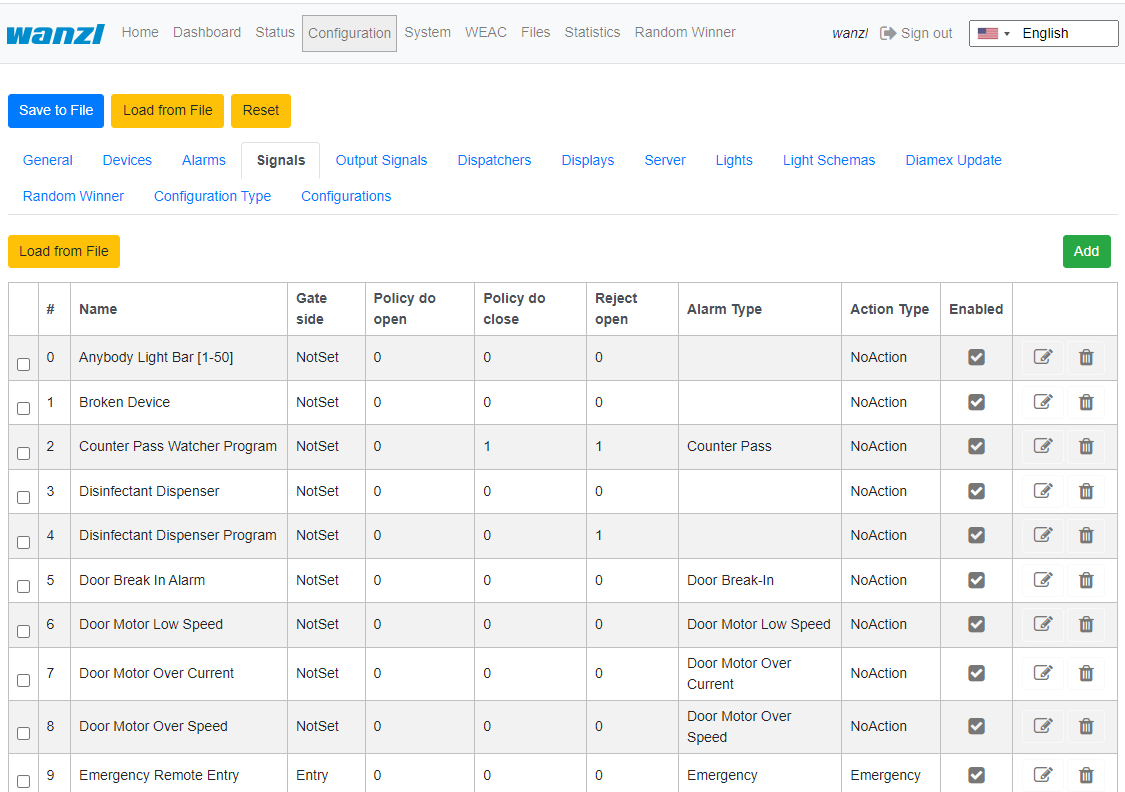
- Signale
- 4 Technischer Hintergrund
- 5 Funktionen 6 Tipps zum Arbeiten
- 4 Technical Background
- 5 Functions
- 6 Tips for Working
- 7 Verwandte Themen
AllgemeinIntroduction[Bearbeiten | Quelltext bearbeiten]
Das Dokument beschreibt die Funktionen und die Konfigurationsmöglichkeiten der Software The document describes the functions and configuration options of the software Facility Management Control Unit.
Die The Facility Management Control Unit ist eine Software zur Steuerung von Zutrittskontrollen. Diese Komponenten können in einem abgeschlossenen Bereich wie einem Sport- oder Unterhaltungszentrum, einer Zone auf einem Flughafen, in Universitäten oder in Sicherheitsbereichen eingesetzt werden. Die Hauptkomponenten der Softwarelösung umfassen:
- Eine automatisierte Durchgangskontrolle mit zweigeteilter Tür- und Signalbeleuchtung
- Barcode- (oder / und RFID-) Scanner, die Identifikationsdaten vom Ticket oder der Karte des Kunden lesen
- Tracking-Kamera, die den Durchgangsweg der Kunden beobachten
- Infobildschirme, die dem Kunden Informationen zum Ein- und Ausgang anzeigen
- Ein oder mehrere externe Lautsprecher
- Ein oder mehrere zusätzliche Monitore mit Inhalten, die auf die Kundenbedürfnisse zugeschnitten sind
Die Hauptmerkmale beinhalten:
- Öffnen der Zutrittskontrolle bei erfolgreicher Validierung des Ticktes
-
Interaktion mit dem Kunden als Reaktion verschiedener Ereignisse durch:
- Lichteffekte
- Sprachansagen über interne oder externe Lautsprecher
- Akustische Bestätigung des Leseprozesses von Barcode-Scannern
- Visuelle Inhalte, die auf einem Infobildschirm angezeigt werden
- Sicheres Öffnen und Schließen der Schwenktüren durch Überwachung des Durchgangsbereichs
Unterstützte Betriebsarten:
- Normal
- Service
- Feueralarm
- Notfall
Ticketeintrittsvarianten:
- Einzeleintrittskarte mit Schließen der Zutrittskontrolle nach dem Durchgang einer Person
- Mehrfacheintrittskarte mit Daueröffnung der Zutrittskontrolle
- einstellbare Zeitintervalle
- Berücksichtigung zusätzlicher Bedingungen über potentialfreie Kontakte
Technische Information[Bearbeiten | Quelltext bearbeiten]
Konfiguration[Bearbeiten | Quelltext bearbeiten]
Schritt 1
Nachdem die Software heruntergeladen und auf die eMMC Karte nach dem dokumentierten Verfahren übertragen worden ist, siehe herzu auch Galaxy Gate Inbetriebnahme, erscheint nach dem ersten Starten der Anmeldebildschirm. Nachdem man sich mit dem Benutzer Installer angemeldet hat, wird der Assistent mit der Definition der IP-Konfiguration gestartet.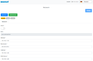
is software for access control management. It can be used in an enclosed area such as a sports or entertainment center, an airport zone, universities or security areas. The main components of the software solution are:
- An automated passage control with two-part door and signal lighting
- Barcode (or/and RFID) scanners that read identification data from the customer's ticket or card
- Tracking cameras observing the passage of customers
- Info screens showing inbound and outbound information to the customer
- One or more external speakers
- One or more additional monitors with content tailored to customer needs
The main features are:
- Opening access control upon successful ticket validation
-
Interaction with customer in response to various events through:
- Light effects
- Voice prompts through internal or external speakers
- Acoustic confirmation of the reading process from barcode scanners
- Visual content displayed on an info screen
- Safe opening and closing of the swing doors by monitoring the passage area
Supported operating modes:
- Normal
- Service
- Fire alarm
- Emergency
The variants of Entry Tickets:
- Single entry ticket with closing of access control after passage of one person
- Multiple entry ticket with permanent access control
- Adjustable time intervals
- Consideration of additional conditions about potential-free contacts
Initial Configuration[Bearbeiten | Quelltext bearbeiten]
After the software has been downloaded and transferred to the eMMC card according to the documented procedure, see also here Galaxy Gate Inbetriebnahme/en, the login screen appears after the first start. After logging in with the user Installer, configuration wizard will be started.
Network[Bearbeiten | Quelltext bearbeiten]
First step is the network settings configuring 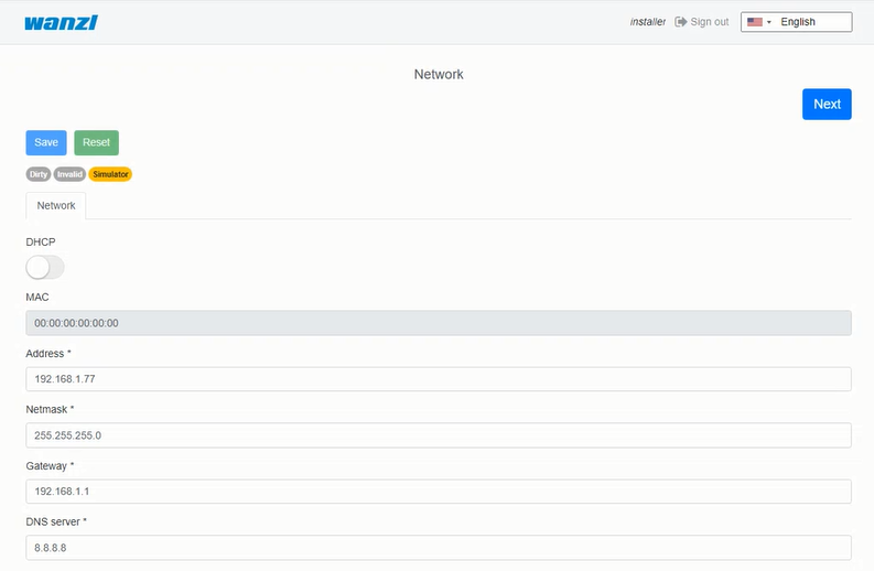
| Parameter | Description | Default Value |
|---|---|---|
| Address | IP-Address of access control | 192.168.1.100 |
| Maske Mask Netzwerkmaske | Network-Mask | 255.255.255.0 |
| Gateway | Gateway-Adresse Address | 192.168.1.1 |
| DNS-Server | DNS-Server für die Namensauflösung for name resolution | 192.168.1.1 |
FMCU Configuration[Bearbeiten | Quelltext bearbeiten]
Next step is selecting FMCU Configuration 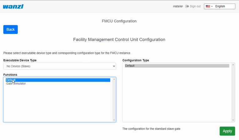
Als Typ kann man im Assistenten grundsätzlich diese Auswahl vornehmen.
As a type, you can basically make this selection in the assistant.
| Selection | Description |
|---|---|
| No Device Slave | Slave Unit (StandardauswahlDefault Selection) |
| Galaxy Gate (Modbus Serial) | Master-Unit mit serieller Verbindung zu Slave-Unit |
| Galaxy Gate (Modbus TCP) | Master-Unit mit Netzwerkverbindung zu with network connection to Slave-Unit |
| Galaxy Port (Modbus Serial) | Unit mit serieller Verbindung zu with serial connection to Slave-Unit |
| Galaxy Port (Modbus TCP) | Unit mit Netzwerkverbindung zu with network connection to Slave-Unit |
 Nachdem die Eingabefelder ausgefüllt worden sind, kann man auf Weiter klicken, um die nächste Seite des Assistenten zu erreichen.
 Auf der nächsten Seite des Assistenten wird die aktuelle WEAC-Firmware angezeigt. Bei Bedarf kann man ein Down oder Upgrade der Firmware durchführen.
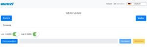 Die Version der Firmware für jede Unit wird als Label neben dem Aktivierungsbutton aufgeführt. Während des Aktualisierungsvorganges werden die Navigationsmöglichkeiten deaktiviert. Der Aktualisierungsprozess dauert ca. 3 Minuten für beide Units.
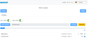 Nach dem Prüfen der WEAC-Firmware werden die Schwenktüren konfiguriert. Dabei wird automatisch geprüft, ob die Mindestvoraussetzungen bzgl. der Firmware erfüllt werden. In der Oberfläche wird man darüber informiert, wenn zunächst die Firmware aktualisiert werden muss.
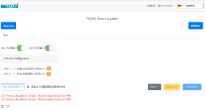 Wenn die Voraussetzungen erfüllt werden, kann man die Schwenktüren auswählen und auf das Gate anwenden.
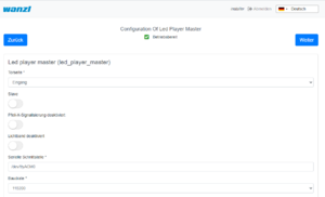
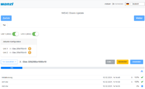 Im nächsten Schritt wird die Konfiguration des LED-Player für beide Units (Master und Slave) durchgeführt. Bei Bedarf kann man die Parameter anpassen. Wenn der Zustand betriebsbereit angezeigt wird, sind keine Modifikationen notwendig.
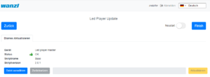
 Auf der letzten Seite des Assistenten wird noch einmal die aktuelle Firmware des LED-Player dargestellt. Optional kann man die Konfiguration mit einem Neustart beenden. Jedoch ist dies nur dann erforderlich, wenn sich IP-Adressen oder Schnittstelleinformationen geändert haben.
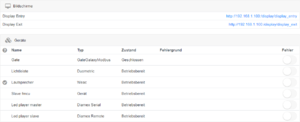
 Nachdem man auf Finish geklickt hat, kann man sich jetzt mit einem bekannten Anmeldeinformationen erneut anmelden und mit dem Galaxy Gate arbeiten. Wenn man sich erneut mit dem Benutzer Installer anmeldet, erhält man eine grafische Übersicht, kann sich über den Status der Zutrittskontrolle informieren und kann bei Bedarf Aktualisierungen durchführen. Damit ist die Einrichtung der Zutrittskontrolle abgeschlossen.
 Man kann sich nun mit einem Service-Account anmelden und weitere Tests durchführen.
Bedienungsanleitung[Bearbeiten | Quelltext bearbeiten]
Konfiguration der Schwenktüren[Bearbeiten | Quelltext bearbeiten] Die Schwenktüren können unterschiedliche Abmaße besitzen, Je nach Breite und Höhe ergeben sich hierdurch andere Sollparameter für einen optimalen Kurvendurchlauf.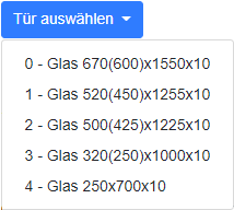 Nachdem ein Typ ausgewählt worden ist, kann man alle Parameter entsprechend den Bedürfnissen in der Oberfläche anpassen, bevor diese dann über den Button Anwenden in der Konfiguration auf der Zutrittskontrolle aktiviert werden. Wenn man einzelne Werte in der Anzeige ändert, müssen die Einstellungen zunächst gespeichert werden. Dazu klick man links in der Oberfläche über der Dateiliste auf das Diskettensymbol.
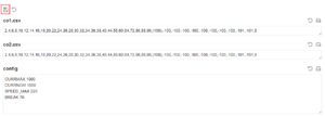 Nachdem die Veränderungen gespeichert worden sind, kann man diese dann über den Button Anwenden aktivieren. Konfiguration des
| Funktion Function | Beschreibung Description |
|---|---|
| AEA | Konfiguration für Configuration for Boarding Gates |
| Sofortige Schließung | Schließen der Schwenkarme ohne Schwenkbereichsüberwachung |
| Mehrfachöffnung | Schwenkarme bleiben offen, wenn mehrere Eingangssignale anliegen |
| Personenschutz | Schließen der Schwenkarme mit Schwenkbereichsüberwachung |
| Einmalöffnung | Einzeldurchgang auch bei Anliegen von mehreren Einangssignalen |
| Rollkoffer | Unterstützung von Rollkoffer ohne Alarm |
| Rollstuhl | Unterstützung von Rollstuhl ohne Alarm |
| Konfigurationstyp | Beschreibung |
|---|---|
| AEA | Konfiguration für Boarding Gates |
| Einmalöffnung Personenschutz | Schließen der Schwenkarme mit Schwenkbereichsüberwachung |
| Einmalöffnung sofortige Schließung | Schließen der Schwenkarme ohne Schwenkbereichsüberwachung |
| Einmalöffnung Rollkoffer | Einzeldurchgang mit Rollkoffer auch bei Anliegen von mehreren Eingangssignalen |
| Einmalöffnung Rollstuhl | Einzeldurchgang mit Rollstuhl auch bei Anliegen von mehreren Eingangssignalen |
| Mehrfachöffnung Personenschutz | Schließen der Schwenkarme mit Schwenkbereichsüberwachung |
| Mehrfachöffnung sofortige Schließung | Schließen der Schwenkarme ohne Schwenkbereichsüberwachung |
| Mehrfachöffnung Rollkoffer | Schwenkarme bleiben offen, wenn mehrere Personen mit Rollkoffer durchgehen |
| Mehrfachöffnung Rollstuhl | Schwenkarme bleiben offen, wenn mehrere Personen mit Rollkoffer durchgehen |
| Immediate Closure | Closing the swivel arms without swivel range monitoring |
| Multiple Opening | Swivel arms remain open when multiple input signals are present |
| Personal Protection | Closing the swivel arms with swivel area monitoring |
| One-time opening | Single pass even when several input signals are present |
| Trolley Case | Support of trolley case without alarm |
| Wheelchair | Assistance from wheelchair without alarm |
| Configuration Type | Description |
|---|---|
| AEA | Configuration for Boarding Gates |
| One-time opening Personal Protection | Closing the swivel arms with swivel area monitoring |
| One-time opening Immediate Closure | Closing the swivel arms without swivel range monitoring |
| One-time opening Trolley Case | Single passage with trolley case even when several input signals are present |
| One-time opening Wheelchair | Single passage with a wheelchair even if several input signals are present |
| Multiple opening personal protection | Closing the swivel arms with swivel area monitoring |
| Multiple opening instant closure | Closing the swivel arms with swivel area monitoring |
| Multi-opening trolley case | Swivel arms remain open when several people with wheeled suitcases pass through |
| Multiple opening wheelchair | Swivel arms remain open when several people with wheeled suitcases pass through |
Meta information[Bearbeiten | Quelltext bearbeiten]
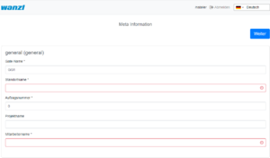
Next step is filling meta information about FMCU 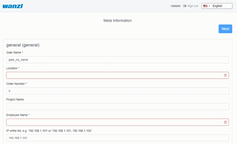
After the input fields have been filled in, you can click on Next to reach the next page of the wizard.
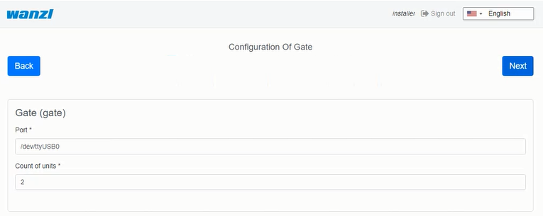
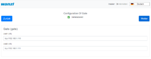
Configuration of Gate[Bearbeiten | Quelltext bearbeiten]
WEAC Firmware Update[Bearbeiten | Quelltext bearbeiten]
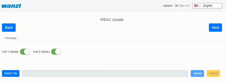
The current WEAC firmware is displayed on the next page of the wizard. If necessary, you can down or upgrade the firmware.
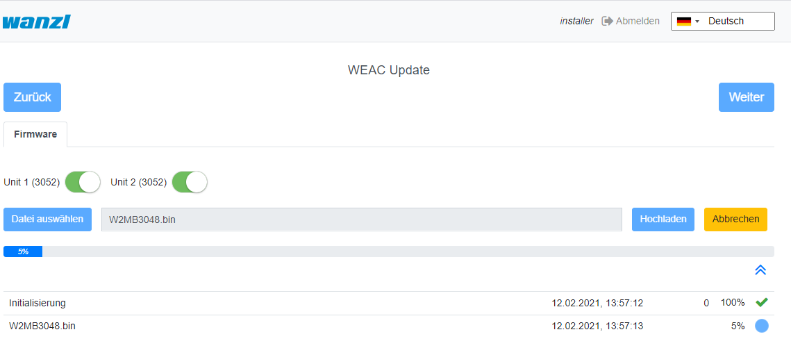
The firmware version for each unit is listed as a label next to the activation button. The navigation options are deactivated during the update process. The update process takes about 3 minutes for both units.
After checking the WEAC firmware, the swing doors are configured. It is automatically checked whether the minimum requirements regarding the firmware are met. You will be informed on the surface if the firmware has to be updated first.
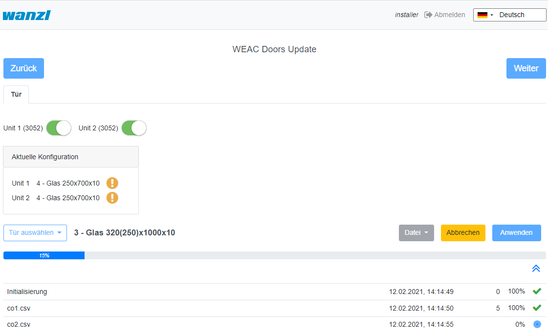
WEAC Doors Update[Bearbeiten | Quelltext bearbeiten]
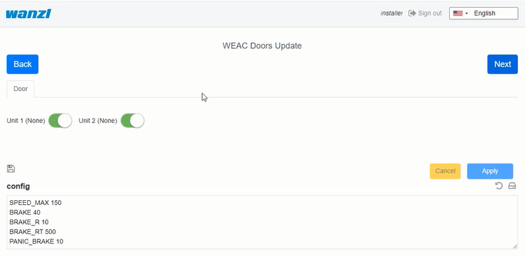
If the requirements are met, you can select the swing doors and apply them to the gate.
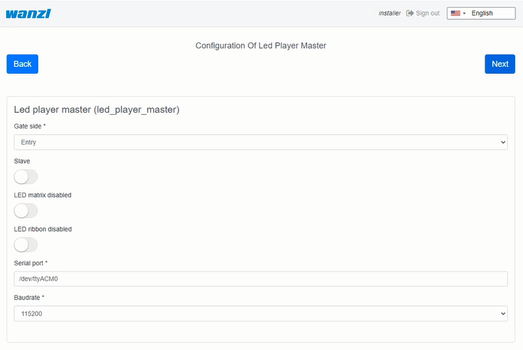
Configuring the Led Player[Bearbeiten | Quelltext bearbeiten]
The next step is to configure the LED player for both units (Master and Slave) accomplished. If necessary, you can adjust the parameters. If the status is ready for use, no modifications are necessary.
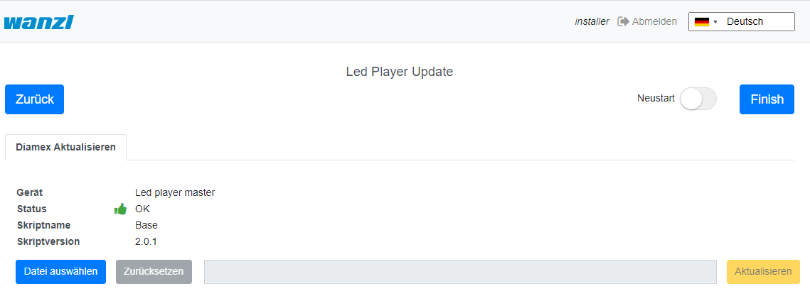
The current firmware of the LED player is shown again on the last page of the assistant. Optionally, you can end the configuration with a restart. However, this is only necessary if IP addresses or interface information have changed.
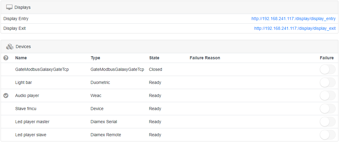
After clicking Finish you can log in again as certain user and work with the Galaxy Gate. If you log in again as user installer, you get a graphical overview, can find out about the status of the access control and can carry out updates if necessary. So you complete the setup of the access control.
You can now log in with a service account and carry out further tests.
Operation Manual[Bearbeiten | Quelltext bearbeiten]
Configuration of the Swing Doors[Bearbeiten | Quelltext bearbeiten]
The swing doors can have different dimensions. Depending on the width and height, this results in other target parameters for optimal curve passage. 
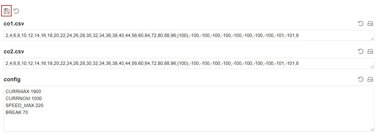
After a type has been selected, all parameters can be adjusted according to the needs in the interface before they are then activated via the button Apply in the configuration on the access control. If you change individual values in the display, the settings must first be saved. To do this, click on the diskette symbol on the left of the interface above the file list.
After the changes have been saved, you can activate them using the Apply button.
Configuration of the XOVIS Sensors[Bearbeiten | Quelltext bearbeiten]
Add XOVIS-Sensor hinzufügen
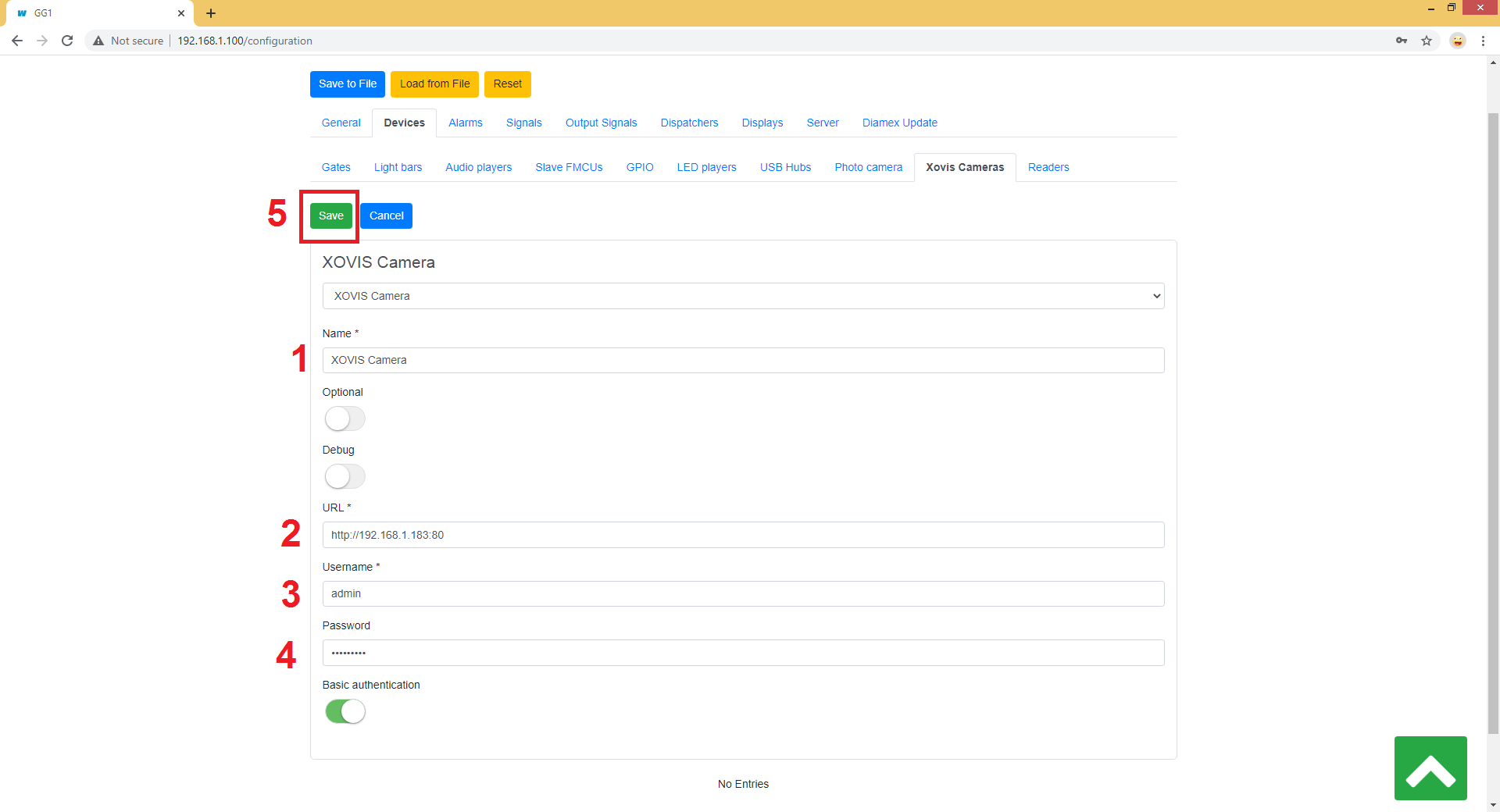
Navigieren Sie zuNavigate to "Configuration" -> "Devices" -> "Xovis Cameras"
und klicken Sie dann auf den Button "Hinzufügen (Add)" Folgende Felder werden in der dargestellten Reihenfolge gefüllt
and then click on the "Add" button
The following fields are filled in the order shown:
- Name
- URL
- Benutzername (Username)
- Passwort (Password)
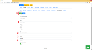 Die Konfiguration wird mit dem Klick auf den Button Save (Speichern) gesichert
The configuration is saved by clicking the Save button.
XOVIS-Überwachungsbereich als Alarmsignal hinzufügen
Navigieren Sie zuAdd XOVIS monitoring area as alarm signal
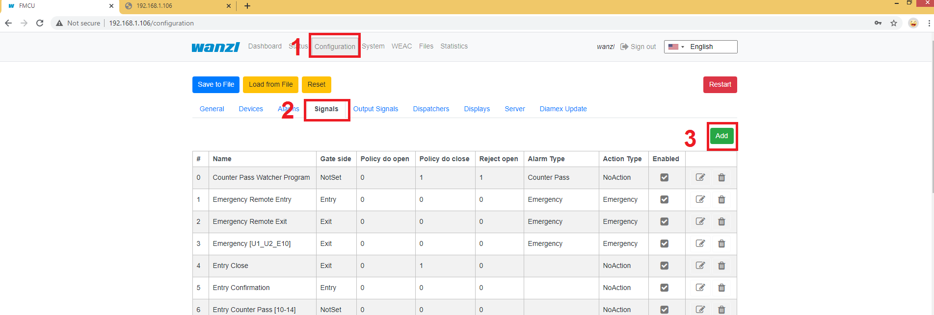
Navigate to "Configuration" -> "Signals"
und klicken Sie dann auf den Button "Hinzufügen (Add)"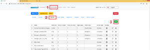 Hier müssen folgende Felder ausgefüllt werden: Wählen Sie Typ
and then click on the "Add" button
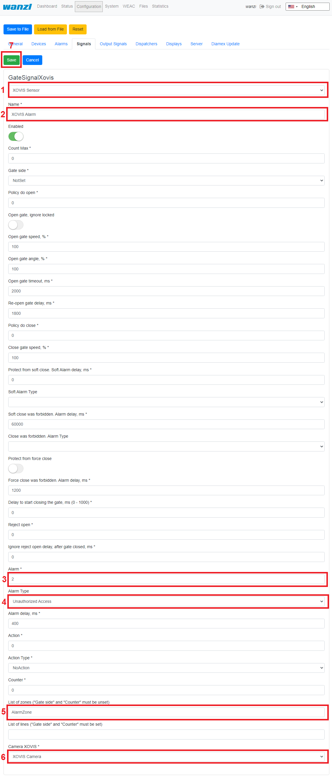
The following fields must be filled in here:
- Select type "XOVIS Sensor" ausLegen Sie den Name des Signals fest (z.B
- Specify the name of the signal (e.g. "XOVIS ALARM")
- Legen Sie die minimale Anzahl der Personen in der Alarmzone fest, bei der ein Alarm ausgelöst werden soll (z.B. 2)
- Wählen Sie den Alarm Typ aus (z.B. "Unauthorisierter Zugriff")
- Bestimmen Sie eine Liste der Alarmzonen (z.BSet the minimum number of people in the alarm zone to trigger an alarm (e.g. 2)
- Select the alert type (e.g. "Unauthorized Access")
- Determine a list of alarm zones (e.g. "AlarmZone")
- Wählen Sie den XOVIS Sensor, der zu hinzugefügt wurde.
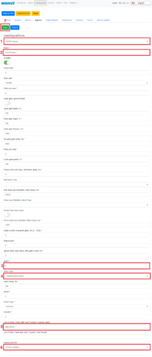 XOVIS-Zähler hinzufügen Navigieren Sie zu
- Select the XOVIS sensor added to.
The configuration is saved by clicking the Save button.
Add XOVIS counter
Navigate to "Configuration" -> "Signals"
und klicken Sie dann auf den Button "Hinzufügen (Add)" Hier müssen folgende Felder ausgefüllt werden: Wählen Sie Typ
and then click on the "Add" button
The following fields must be filled in here:
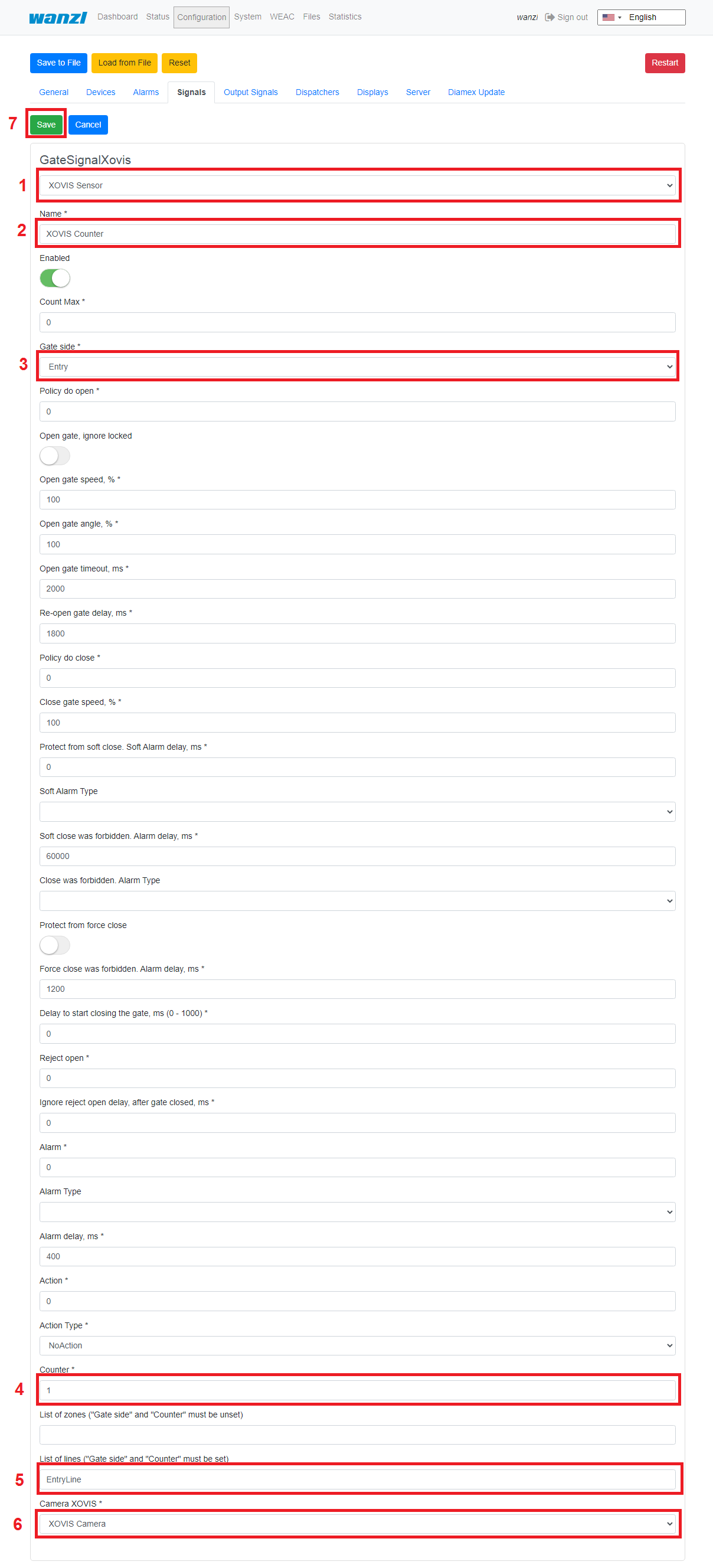
- Select type "XOVIS Sensor" ausLegen Sie den Name des Signals fest (z.B.
- Specify the name of the signal (e.g. "XOVIS Counter")
- Bestimmen Sie die Seite des Gates (z.B. "Eingang")
- Legen Sie den Wert "Counter" fest,.
- Bestimmen Sie eine Liste der Linien(z.BSpecify the side of the gate (e.g. "Entrance")
- Set the value "Counter".
- Specify a list of lines(e.g. "EntryLine")
- Wählen Sie die XOVIS Kamera, welche Sie vorher hinzugefügt haben aus.
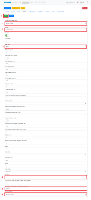 VPN-Schlüssel hinterlegen
- Select the XOVIS camera that you added earlier.
The configuration is saved by clicking the Save button.
Store VPN key[Bearbeiten | Quelltext bearbeiten]
Für die Nutzung der Fernwartung wird ein VPN-Schlüssel benötigt. Dieser Schlüssel kann bei Angabe des Projektnamens (Ansicht Konfiguration->Allgemein) beim Support (support@maxcrc.de) von maxcrc angefragt werden.
Nachdem die Schlüsseldatei A VPN key is required to use remote maintenance. This key can be requested from maxcrc support (support@maxcrc.de) by specifying the project name (Configuration->General view).
After the key file (*.opvn.conf) vorliegt, kann man über die Seite is available, you can import via the System->OpenVPN den Import vornehmen. Dazu sind folgende Schritte notwendig.
Navigation zu der Seitepage. The following steps are necessary for this.
Navigating to the System-OpenVPN page.

 Diese Datei wird jetzt über den Button Datei auswählen im Dateiauswahldialog angegeben. Danach klickt man auf Hochladen. Wenn der Vorgang erfolgreich abgeschlossen worden ist, erscheint ein Info Symbol neben dem Start-Button. Das bedeutet, die Datei wurde erfolgreich hochgeladen, der OpenVPN Client kann nun durch Klicken auf Start aktiviert werden.
 Wenn der Start erfolgreich war, wechselt die Farbe von grün nach rot und die Beschriftung von Start zu Halt. Rechts neben dem Info-Symbol wird der Status des OpenVPN-Clients angezeigt sowie die IP-Adresse für den Zugriff im VPN-Netzwerk für dieses Gate eingeblendet. Man kann den Fernzugriff deaktivieren, indem man den Button Halt klickt.
Softwareupdates[Bearbeiten | Quelltext bearbeiten]
Bei fehlender Internetverbindung kann man im Menü System->Software aktualisieren einzelne Paketinstallationen durchführen. Dazu stellt man vorher ein zip-Archiv mit den zu installierenden Paketen zusammen. Es ist darauf zu achten dass in dem Archiv keine relativen Pfade verwendet werden. Danach kann man das Archiv über Datei auswählen in die Eingabezeile einfügen und die Updateprozedur mit Hochladen starten. Der Fortschrittsprozess wird in der Oberfläche angezeigt.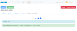 Anzeige während der Installation
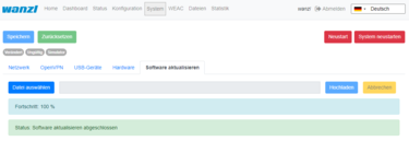 Anzeige nach Abschluss der InstallationBei Bedarf kann die Anwendung neu gestartet werden.
Kundenrolle[Bearbeiten | Quelltext bearbeiten]
Wenn man sich mit dem Benutzer Client anmeldet, erscheint eine vereinfachte Oberfläche mit lediglich drei KonfigurationsmenüsThis file is now specified via the Select file button in the file selection dialog. Then click on Upload. When the process has been successfully completed, an info icon will appear next to the start button. This means the file has been uploaded successfully, the OpenVPN client can now be activated by clicking on Start.
If the start was successful, the color changes from green to red and the label from start to stop. The status of the OpenVPN client and the IP address for access in the VPN network for this gate are displayed to the right of the info symbol. You can disable remote access by clicking the Stop button.
Update Software[Bearbeiten | Quelltext bearbeiten]
If there is no Internet connection, individual package installations can be carried out using the System->Update software menu. You should have a zip archive with the packages to be installed. It must be ensured that no relative paths are used in the archive. Then you can insert the archive into the input line via Select file and start the update procedure with Upload. The progress of update process is displayed: 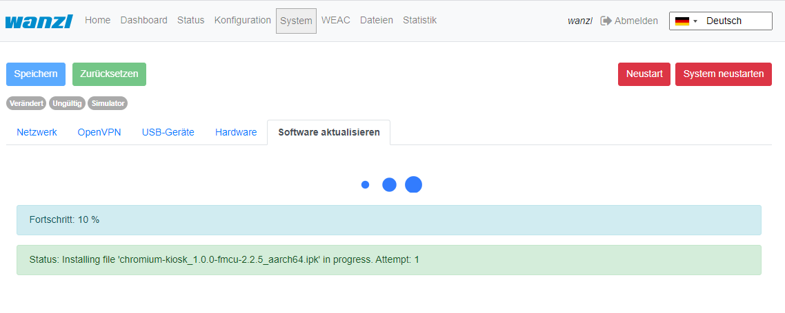

If necessary, the application can be restarted.
Customer Role[Bearbeiten | Quelltext bearbeiten]
When you log in as user client, a simplified interface appears with "Home", "Status", "
Statistik
Statistics" configuration menus. 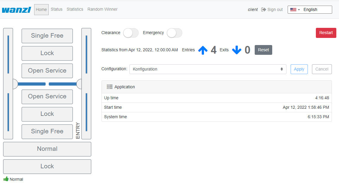
 In dieser Ansicht kann man die Zutrittskontrolle administrieren, jedoch keine Konfigurationsanpassungen durchführen. Dia aktuellen Statistiken werden direkt auf der Oberfläche angezeigt, eine vollständige Übersicht der Zutritte kann man im Reiter Statistik einsehen und bei Bedarf exportieren. Der aktuelle Zustand der einzelnen Komponenten der Zutrittskontrolle kann im Reiter Status eingesehen werden. Die Option Reinigung deaktiviert alle Alarmmeldungen, um die Arbeit des Reinigungspersonals zu erleichtern. Die Option Notauf unterstützt den Anwender bei einer sofortigen Öffnung der Zutrittskontrolle. Standardbelegung Anschlussboard
In this view you can administrate the access control, but you cannot make any configuration adjustments. The current statistics are displayed directly on the interface, a complete overview of the accesses can be viewed in the Statistics tab and exported if required. The current status of the individual access control components can be viewed in the Status tab. The Clearance option disables all alarms to make the cleaning staff's job easier. The Emergency option supports the user in opening the access control immediately.
Standard Assignment Connection Board[Bearbeiten | Quelltext bearbeiten]
Unit 1
| Anschluss Port | Funktion Function | Beschreibung Description |
|---|---|---|
| LSU (E1) | LS Middle
Lichtschranke Mitte Center Light barrier |
NO
Schließerkontakt Normally Open Contact |
| LSV (E2) | LS Entry
Lichtschranke Eingang Photocell Input |
NO
Schließerkontakt normally open contact |
| E3 | Open Entry
Einzelfrei Eingangsrichtung Single free entry direction Impuls 0,1-1,0 Sek. |
NO
Schließerkontakt Normally Open Contact |
| E4 | Open Exit
Einzelfrei Ausgangsrichtung Single free exit direction Impuls 0,1-1,0 Sek. |
NO
Schließerkontakt normally open contact |
| LSH (E5) | NA
nicht angeschlossen not connected |
|
| E6 | State bit 0
Zustandsbit Status bit 0 |
NO
Schließerkontakt normally open contact |
| E7 | State bit 1
Zustandsbit Status bit 1 |
NO
Schließerkontakt normally open contact |
| E8 | Fire Alarm
Brandmeldeanlage fire alarm system (BMA) |
NC
Öffnerkontakt normally closed contact |
| E9 | Open Entry 70%
Einzelfrei 70% Eingangsrichtung Input Direction Impuls 0,1-1,0 Sek. |
NO
Schließerkontakt normally open contact |
| E10 | Emergency Open Button
Notauftaster emergency button |
NC
Öffnerkontakt normally closed contact |
| A8 | Entry Confirmation
Durchgangsbestätigung Eingangsrichtung Confirmation of passage entry direction Impuls 0,5 Sek. |
+12 VDC |
| A9 | Exit Confirmation
Durchgangsbestätigung Ausgangssrichtung Confirmation of passage exit direction Impuls 0,5 Sek. |
+12 VDC |
| Anschluss Port | Funktion Function | Beschreibung Description |
|---|---|---|
| LSU (E1) | NA
nicht angeschlossen not connected |
|
| LSV (E2) | NA
nicht angeschlossen not connected |
|
| E3 | Open Entry
Einzelfrei Eingangsrichtung Single free entry direction Impuls 0,1-1,0 Sek. |
NO
Schließerkontakt normally open contact |
| E4 | Open Exit
Einzelfrei Ausgangsrichtung Single free exit direction Impuls 0,1-1,0 Sek. |
NO
Schließerkontakt normally open contact |
| LSH (E5) | LS Exit
Lichtschranke Ausgang Photocell exit |
NO
Schließerkontakt normally open contact |
| E6 | State bit 2
Zustandsbit Status bit 2 |
NO
Schließerkontakt normally open contact |
| E7 | State bit 3
Zustandsbit status bit 3 |
NO
Schließerkontakt normally open contact |
| E8 | Fire Alarm
Brandmeldeanlage fire alarm system (BMA) |
NC
Öffnerkontakt normally closed contact |
| E9 | Open Exit 70%
Einzelfrei single free 70% Ausgangsrichtung exit direction Impuls 0,1-1,0 Sek. |
NO
Schließerkontakt normally open contact |
| E10 | Emergency Open Button
Notauftaster emergency button |
NC
Öffnerkontakt normally closed contact |
| A8 | Alarm Impuls
Alarm Impuls 0,5 Sek. |
+12 VDC |
| A9 | Gate State Error
Fehlerzustand error condition Durchgang |
+12 VDC |
| Zustand Status | Unit 1 E6
Bit 0 |
Unit 1 E7
Bit 1 |
Unit 2 E6
Bit 2 |
Unit 2 E7
Bit 3 |
|---|---|---|---|---|
| Normal
Normal |
0 | 0 | 0 | 0 |
| Free Entry
Eingang Dauerfrei Entrance permanently free |
1 | 0 | 0 | 0 |
| Lock Entry
Eingang gesperrt entrance blocked |
0 | 1 | 0 | 0 |
| Service Entry
Daueroffen Eingangsrichtung Permanently open entry direction |
1 | 1 | 0 | 0 |
| Free Exit
Ausgang Dauerfrei Exit permanently free |
0 | 0 | 1 | 0 |
| Free Entry/Exit
Eingang/Ausgang DauerfreiInput/Output permanently free(Not implemented) |
1 | 0 | 1 | 0 |
| Lock Entry / Free Exit
Eingang gesperrt / Ausgang Dauerfrei Entrance blocked / exit permanently free |
0 | 1 | 1 | 0 |
| tbd | 1 | 1 | 1 | 0 |
| Lock Exit
Ausgang gesperrt exit blocked |
0 | 0 | 0 | 1 |
| Free Entry / Lock Exit
Eingang Dauerfrei / Ausgang gesperrt Entrance permanently free / exit blocked |
1 | 0 | 0 | 1 |
| Lock
Gesperrt |
0 | 1 | 0 | 1 |
| tbd | 1 | 1 | 0 | 1 |
| Service Exit
Daueroffen Ausgangsrichtung Permanently open exit direction |
0 | 0 | 1 | 1 |
| tbd | 1 | 0 | 1 | 1 |
| tbd | 0 | 1 | 1 | 1 |
| Self Test
Selbsttest self test |
1 | 1 | 1 | 1 |
AlarmdefinitionAlarms Definition[Bearbeiten | Quelltext bearbeiten]
Ein Alarm wird als Folgeaktion von Signalen oder anderen Quellen (z.B. Geräte) ausgelöst. Ein Alarm besteht hat mehrere allgemeine Eigenschaften. Dazu gehören ein Name, die Definition einer Aktion...
Signale[Bearbeiten | Quelltext bearbeiten]
Die Informationen in diesem Abschnitt basieren auf der FMCU-Software v2.3.7 und der WEAC-Version 32.14.
Technischer Hintergrund[Bearbeiten | Quelltext bearbeiten]
Die Software FMCU basiert auf einem angepassten UNIX-Betriebssystem, welche unter Anwendung des Yocto-Projektes produziert worden ist. Es werden nur die benötigten Dienste im Betriebssystem aktiviert. Es werden die für den CPU-Typ optimalen Unterstützungspakete bei der Erstellung des Betriebssystems berücksichtigt. Diese sogenannten Board Support Packages (BSP) werden von den Hardwareherstellern zur Verfügung gestellt und gestatten eine optimale und effiziente Ausnutzung der Hardwareressourcen.
Funktionen[Bearbeiten | Quelltext bearbeiten]
Grundsätzlich werden die Funktionen über die Signalverabeitung abgebildet. Die Signale werden durchunterschiedliche Quellen erzeugt. Dazu gehören:
- Lichtleiste
- Lichtsensor
- Deckensensor
- Sonstige
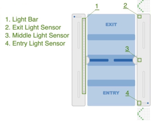 Die Lichtleiste dienst als Quelle für mehrere Signale und ist ebenfalls in unterschiedliche Bereiche unterteilt.
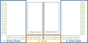 In der Standardkonfiguration sind folgende Signale konfiguriert.
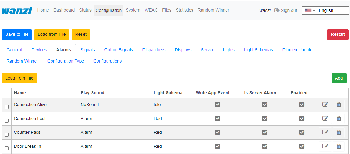
An alarm is triggered as a follow-up action from signals or other sources (e.g. devices). Navigate to "Configuration" -> "Alarms".
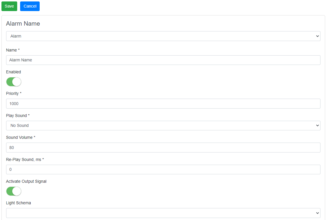
To create the alarm click on the "Add" button:
An alarm has several general characteristics: Name, Enabled Status, Priority, Sounds settings, Light settings, etc.
In the table below there are descriptions of existing alarms.
| Definition | Description | Status |
|---|---|---|
| Connection Alive | monitors connection to external application | on/off |
| Connection Lost | monitors connection to external application | on/off |
| Counter Pass | is set by anti-rotation protection is activated | on/off |
| Door Break-In | Door is forcibly moved when closed | on/off |
| Emergency | is set if the signals on unit 1 E8 or unit 2 E8 are not active (opener). | on/off |
| Fire Alarm | is set if the signals on unit 1 E10 or unit 2 E10 are not active (opener). | on/off |
| Invalid Ticket | is set if ticket validation fails | Impuls |
| Motionless Object | is set when an object is in the gate area for more than a defined period of time and closing is prevented by a timeout. | on/off |
| No Alarm | is set if no alarm is defined for signals | on/off |
| Proceed Alarm | analogous to Motionless Object with a different time span and other actions without light indication | on/off |
| Server Alarm | is triggered in the FMCU server | on/off |
| Tailgating | is set if more than one person is in the gate area | on/off |
| Unauthorized Access | is set if a person is in the gate area when the gate is closed | on/off |
| Valid Ticket | is set if the ticket validation was successful (trigger beep) | Impuls |
Signals[Bearbeiten | Quelltext bearbeiten]
The information in this section is based on FMCU software v2.3.7 and WEAC version 32.14.
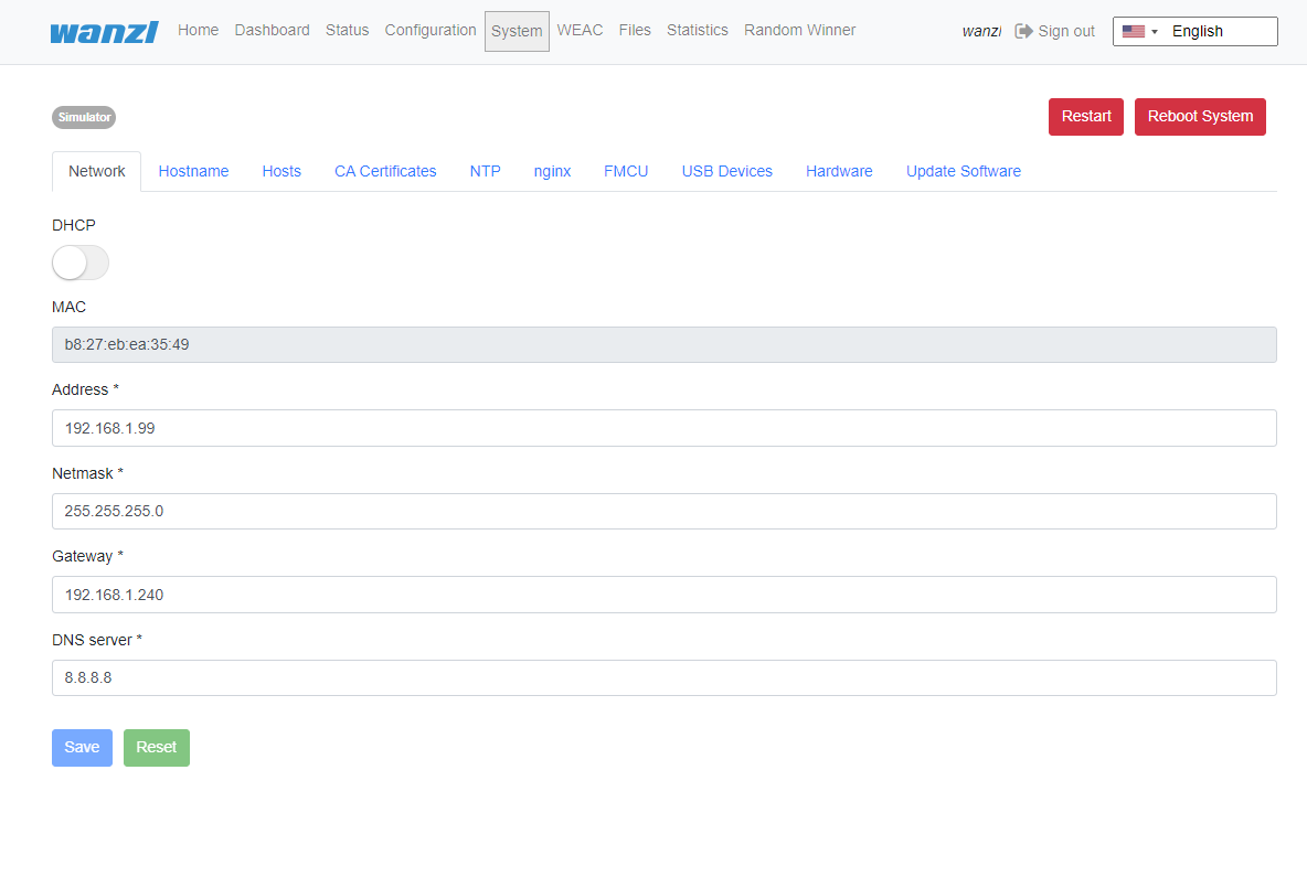
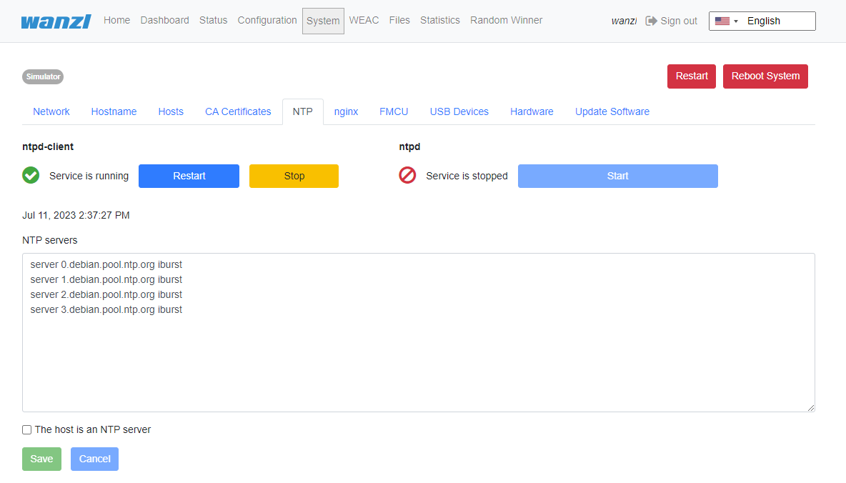
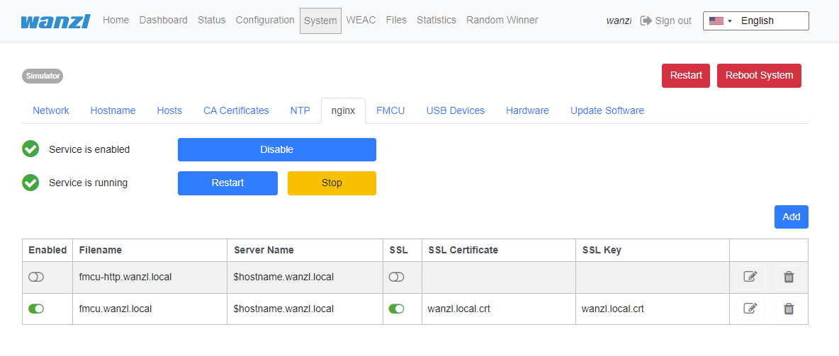
System[Bearbeiten | Quelltext bearbeiten]
The information in this section is based on FMCU software v2.6.14.
Network[Bearbeiten | Quelltext bearbeiten]
Hostname[Bearbeiten | Quelltext bearbeiten]
Hosts[Bearbeiten | Quelltext bearbeiten]
CA Certificates[Bearbeiten | Quelltext bearbeiten]
NTP[Bearbeiten | Quelltext bearbeiten]
nginx[Bearbeiten | Quelltext bearbeiten]
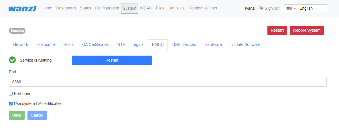
FMCU[Bearbeiten | Quelltext bearbeiten]
Light Schemas[Bearbeiten | Quelltext bearbeiten]
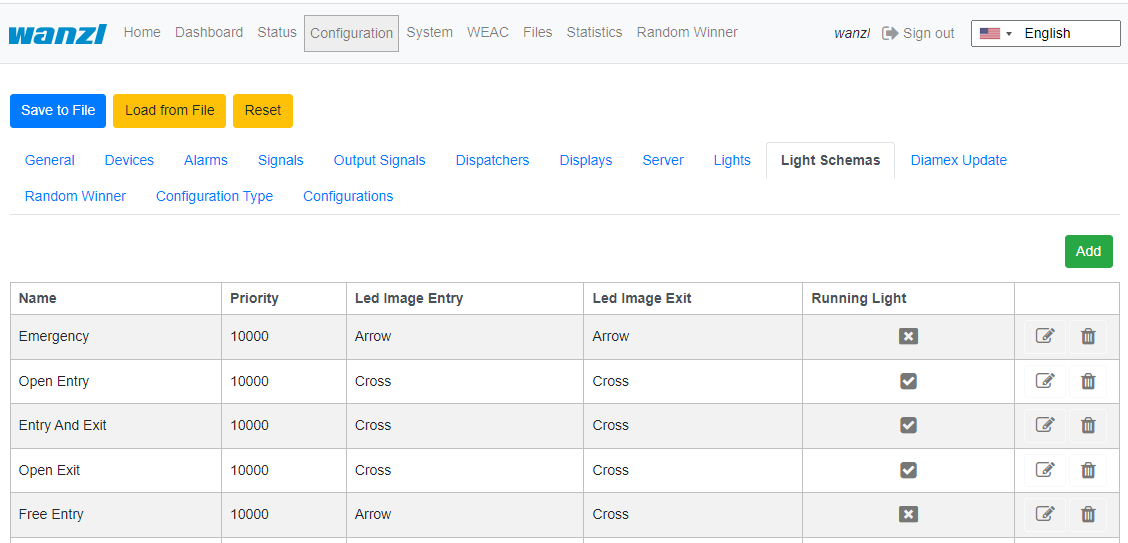
To navigate the section click "Configuration" -> "Light Schemas". Here you can add and/or customize named color schemes.
Each schema describes the colors and behaviour of FMCU lights elements like enter and exit zones and the door. Existing light schema you can use in settings of Gates and Alarms.
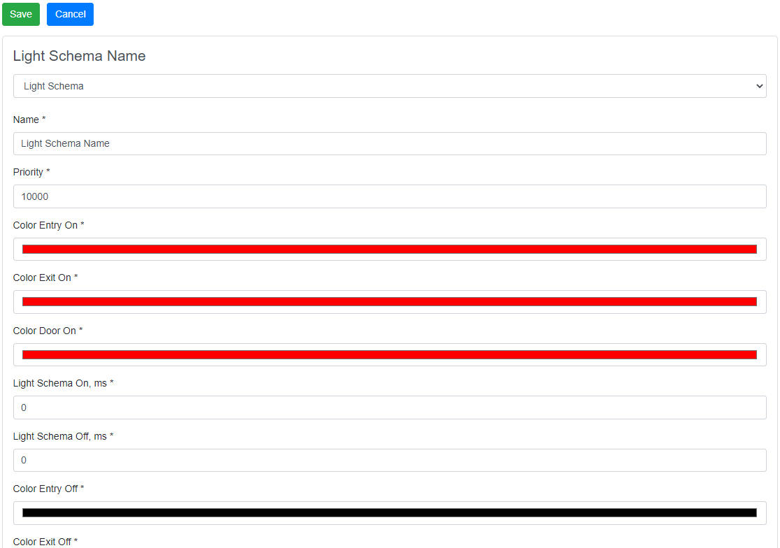
Click Add to create light schema or click "pen" in the table to edit existing schema.
Each light schema is described by the fields below
| Field | Description |
|---|---|
| Name | Name of light schema |
| Priority | Priority of using light schema if there is competition situation. Less value means more priority |
| Color Entry On | Color of the gate entry zone during "On" time period |
| Color Exit On | Color of the gate exit zone during "On" time period |
| Color Door On | Color of the doors during "On" time period |
| Light Schema On, ms * | Length of "On" time period in ms |
| Light Schema Off, ms * | Length of "Off" time period in ms |
| Color Entry Off | Color of the gate entry zone during "Off" time period |
| Color Exit Off | Color of the gate exit zone during "Off" time period |
| Color Door Off | Color of the doors during "Off" time period |
| Led Image Entry * | Selected image of the gate entry zone (Arrow, Cross, Empty) |
| Led Image Exit * | Selected image of the gate exit zone (Arrow, Cross, Empty) |
| Running Light | Using "runing light" for the light schema (option) |
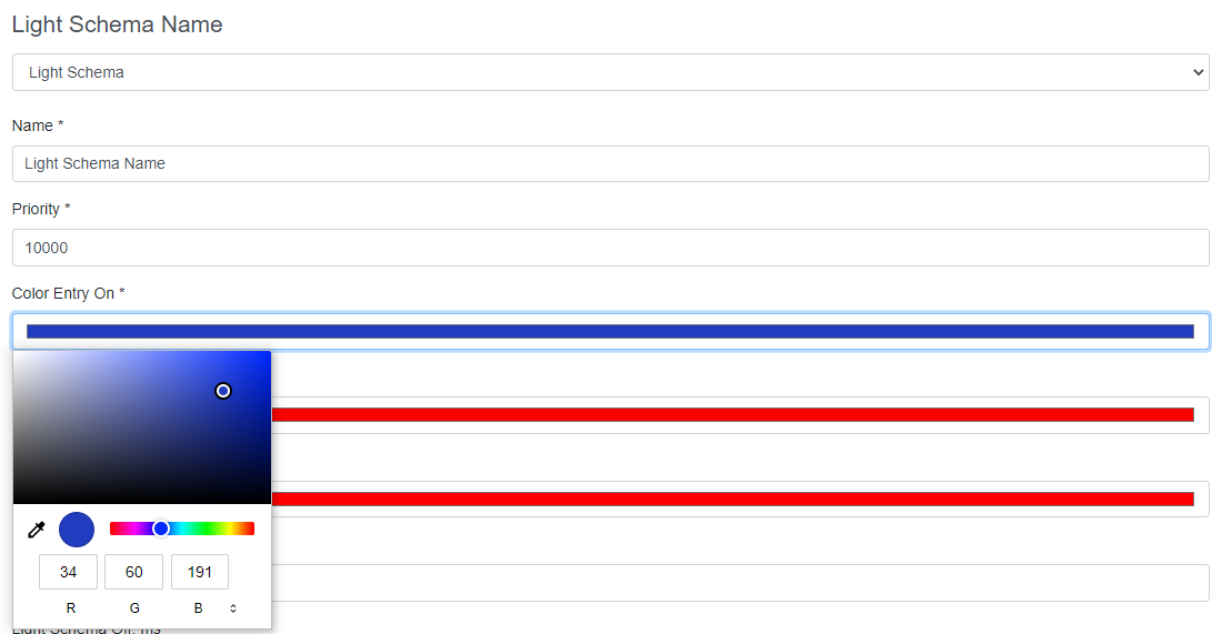
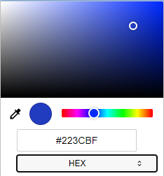
Click on any field for color to edit color of selected gate element
You can select the color space (RGB, HSL, HEX) to set the required color
Lights[Bearbeiten | Quelltext bearbeiten]
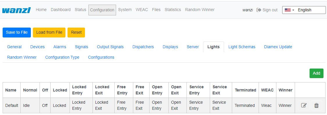
To navigate the section click "Configuration" -> "Lights". Here you can add and/or customize light configurations for different gate's modes.
Each configuration has its own name. The image above shows the default light configuration. Click Add to create configuration, or "pen" to edit existing one.
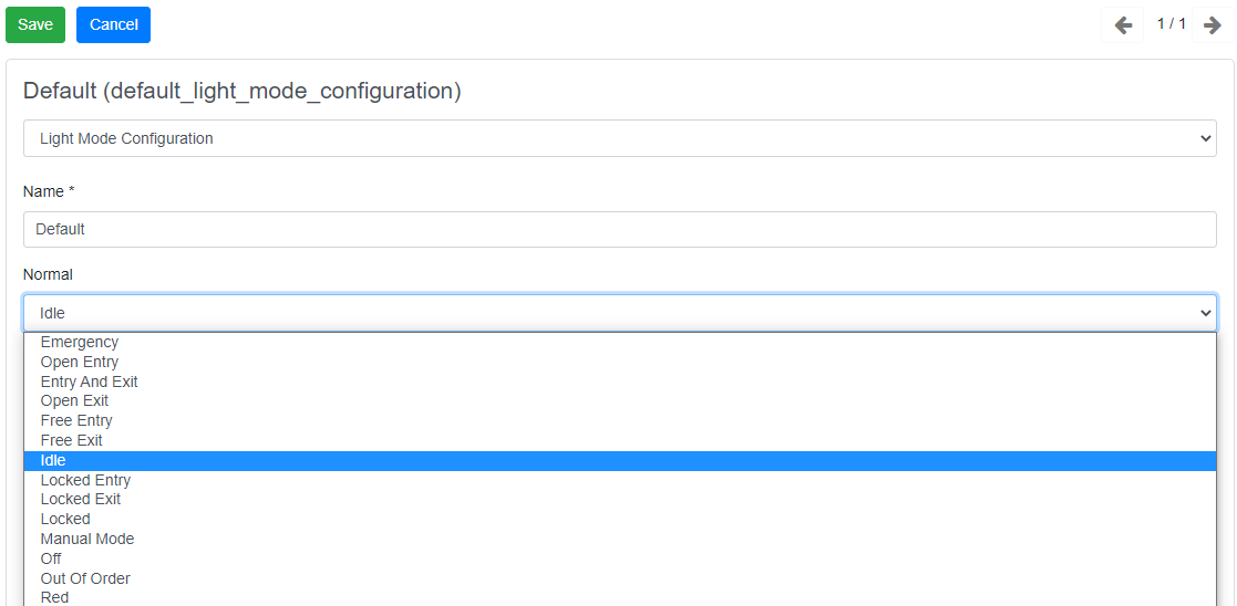
For each mode select existing light schema.
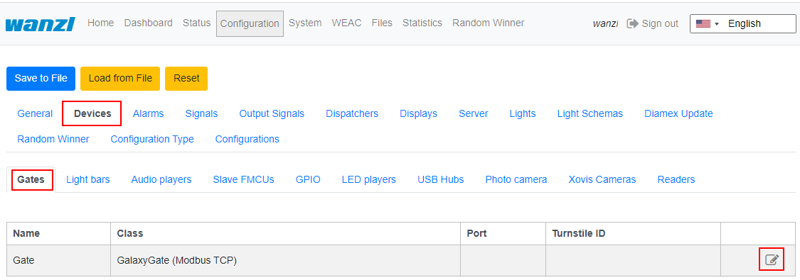
Then you can use the light configuration in "Devices" -> "Gates" settings.
Press "pen" to edit gate settings, and select light configuration.
Technical Background[Bearbeiten | Quelltext bearbeiten]
The FMCU software is based on a customized UNIX operating system, which has been produced using the Yocto Project. Only the required services are activated in the operating system. The optimal support packages for the CPU type are taken into account when creating the operating system. These so-called Board Support Packages (BSP) are provided by the hardware manufacturers and allow optimal and efficient utilization of the hardware resources.
Functions[Bearbeiten | Quelltext bearbeiten]
In principle, the functions are mapped via the signal processing. The signals are generated by different sources including:
- Light bar
- Light sensor
- Ceiling sensor
- Other
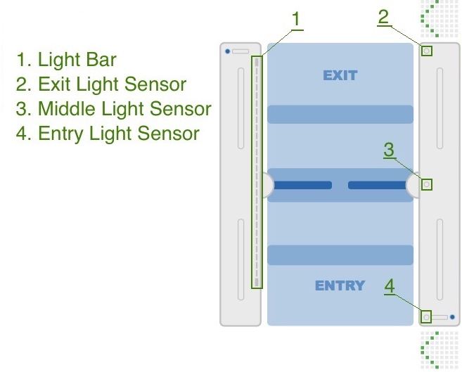
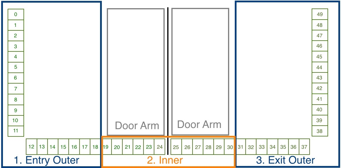
The location of the sensors is shown in the figure below. In each half of the frame there is a so-called "inner zone" and an "outer zone". When passing through an access control, a signal flow diagram is generated, which is used to map the following functions.
The light bar serves as a source for several signals and is also divided into different areas.
The following signals are installed in the standard configuration.
| Signal Name | Frame Half |
|---|---|
| Entry Confirmation | Entry |
| Entry Gate Sensor [U1_E2] | Eingang Entry |
| Entry Outer LightBar | Eingang Entry |
| Exit Inner LightBar | Eingang Entry |
| Free Entry [1000] | Eingang Entry |
| Lock Entry [0100] | Eingang Entry |
| Open Entry [U1_U2_E3] | Eingang Entry |
| Open Entry 70% [U1_E9] | Eingang Entry |
| Remote Open Entry | Eingang Entry |
| Service Entry [1100] | Eingang Entry |
| Emergency Remote | Ausgang Exit |
| Emergency [U1_U2_E8] | Ausgang Exit |
| Entry Inner LightBar | Ausgang Exit |
| Exit Confirmation | Ausgang Exit |
| Exit Gate Sensor [U2_E5] | Ausgang Exit |
| Exit Outer LightBar | Ausgang Exit |
| Free Exit [0010] | Ausgang Exit |
| Lock Exit [0001] | Ausgang Exit |
| Open Exit [U1_U2_E4] | Ausgang Exit |
| Open Exit 70% [U2_E9] | Ausgang Exit |
| Remote Open Exit | Ausgang Exit |
| Service Exit [0011] | Ausgang |
| Exit |
Closing-run at reduced Speed[Bearbeiten | Quelltext bearbeiten]
Diese Funktion ist für Signale zutreffend, die die Eigenschaft This function applies to signals that have the property CloseGate > 0 aufweisen. Bei den betroffenen Signalen muss der Wert . For the affected signals, the value Close gate speed, % * mit einem Wert zwischen 10 und 100% definiert werden. Es besteht somit die Möglichkeit, für unterschiedliche Durchgangszenarien entsprechende Schließgeschwindigkeiten zu definieren. Der Standardwert ist auf 100% festgelegt. In der Standardkonfiguration erfüllen folgende Signale diese Voraussetzung must be defined with a value between 10 and 100%. It is therefore possible to define appropriate closing speeds for different passage scenarios. The default value is set to 100%. In the standard configuration, the following signals meet this requirement.
| Signal | Parameter Wert | Value |
|---|---|---|
| Tailgating watcher | Close gate speed, % * | 100% |
| Entry Gate Sensor [U1_E2] | Close gate speed, % * | 100% |
| Exit Gate Sensor [U2_E5] | Close gate speed, % * | 100% |
| Entry Outer LightBar | Close gate speed, % * | 100% |
| Exit Outer LightBar Exit | Close gate speed, % * | 100% |
DurchgangsbestätigungPassage Confirmation[Bearbeiten | Quelltext bearbeiten]
Diese Funktion setzt einen Impuls mit einer einstellbaren Zeitdauer im Anschlussboard für den Anschluss A8.Zusätzlich wird erfolgte Durchgang in der Statistik berücksichtigt.
KoffertrolleyerkennungThis function sets an impulse with an adjustable duration in the connection board for connection A8.
Suitcase Trolley Detection[Bearbeiten | Quelltext bearbeiten]
Diese Funktion ist aktiv wenn bei folgenden Signalen die aufgeführten Parameter gesetzt werden. Es bedeutet, dass eine Personen mit einem hinter sich herziehenden Koffer ohne Störung durch vorzeitig schleißende Schwenktüren passieren kannThis function is active when the listed parameters are set for the following signals. It means that a person with a suitcase being pulled behind them can pass through prematurely closing swing doors without being disturbed.
| Signal | Parameter Wert | Value |
|---|---|---|
| Middle Gate Sensor [U1_E1] | Protect from force close | true |
| Inner LightBar | Protect from force close | true |
MehrfachöffnungMultiple Opening[Bearbeiten | Quelltext bearbeiten]
Diese Funktion ist nur dann gültig, wenn ein Leser für die Eingangsrichtung eingerichtet worden ist. Es bedeutet, dass mehrere Personen in einer Reihe nacheinander den Eingang passieren können, ohne dass die Schwenktür zwischenzeitlich geschlossen wird. Es muss von jeder Person ein Ticket am Kartenleser am Eingang präsentiert werden. Nur bei erfolgreicher Validierung bleiben die Schwenktüren geöffnet. Diese Funktion ist aktiv wenn bei folgenden Signalen die aufgeführten Parameter gesetzt werdenThis function is only valid if a reader has been set up for the entry direction. It means that several people can pass through the entrance in a row without the swing door being closed in the meantime. Each person must present a ticket at the card reader at the entrance. The swing doors only remain open if the validation is successful. This function is active when the listed parameters are set for the following signals.
| Signal | Parameter Wert | Value |
|---|---|---|
| Middle Gate Sensor [U1_E1] | Protect from force close | true |
| Inner LightBar | Protect from force close | true |
| Entry Outer LightBar | Protect from force close | true |
| Entry Gate Sensor [U1_E2] | Protect from force close | true |
| Tailgating watcher | Aktiviert Activated | false |
Tipps zum ArbeitenTips for Working[Bearbeiten | Quelltext bearbeiten]
Wenn man die Übersicht bei der Konfiguration der Signale verloren hat, kann man über die Funktion If you have lost the overview when configuring the signals, you can use the functionReset to Default
einen definierten Ausgangszustand wiederherstellen restore a defined initial state.Verwandte Themen
{{translate|Gate ~ FMCU Galaxy Gate ~ User Guide}}
{{DISPLAYTITLE:Gate ~ FMCU Galaxy Gate ~ User Guide}}
==Allgemein==
Das Dokument beschreibt die Funktionen und die Konfigurationsmöglichkeiten der Software Introduction==
The document describes the functions and configuration options of the software '''F'''acility '''M'''anagement '''C'''ontrol '''U'''nit.
DieThe Facility Management Control Unit ist eine Software zur Steuerung von Zutrittskontrollen. Diese Komponenten können in einem abgeschlossenen Bereich wie einem Sport- oder Unterhaltungszentrum, einer Zone auf einem Flughafen, in Universitäten oder in Sicherheitsbereichen eingesetzt werden. Die Hauptkomponenten der Softwarelösung umfassen:
*Eine automatisierte Durchgangskontrolle mit zweigeteilter Tür- und Signalbeleuchtung
*Barcode- (oder / und RFID-) Scanner, die Identifikationsdaten vom Ticket oder der Karte des Kunden lesen
*Tracking-Kamera, die den Durchgangsweg der Kunden beobachten
*Infobildschirme, die dem Kunden Informationen zum Ein- und Ausgang anzeigen
*Ein oder mehrere externe Lautsprecher
*Ein oder mehrere zusätzliche Monitore mit Inhalten, die auf die Kundenbedürfnisse zugeschnitten sind
Die Hauptmerkmale beinhalten:
*Öffnen der Zutrittskontrolle bei erfolgreicher Validierung des Ticktes
*Interaktion mit dem Kunden als Reaktion verschiedener Ereignisse durch:
**Lichteffekte
**Sprachansagen über interne oder externe Lautsprecher
**Akustische Bestätigung des Leseprozesses von Barcode-Scannern
**Visuelle Inhalte, die auf einem Infobildschirm angezeigt werden
**Sicheres Öffnen und Schließen der Schwenktüren durch Überwachung des Durchgangsbereichs
Unterstützte Betriebsarten:
*Normal
*Service
*Feueralarm
*Notfall
Ticketeintrittsvarianten:
*Einzeleintrittskarte mit Schließen der Zutrittskontrolle nach dem Durchgang einer Person
*Mehrfacheintrittskarte mit Daueröffnung der Zutrittskontrolle
*einstellbare Zeitintervalle
*Berücksichtigung zusätzlicher Bedingungen über potentialfreie Kontakte
==Technische Information==
===Konfiguration===
'''Schritt 1'''
Nachdem die Software heruntergeladen und auf die eMMC Karte nach dem dokumentierten Verfahren übertragen worden ist, siehe herzu auchis software for access control management. It can be used in an enclosed area such as a sports or entertainment center, an airport zone, universities or security areas. The main components of the software solution are:
*An automated passage control with two-part door and signal lighting
*Barcode (or/and RFID) scanners that read identification data from the customer's ticket or card
*Tracking cameras observing the passage of customers
*Info screens showing inbound and outbound information to the customer
*One or more external speakers
*One or more additional monitors with content tailored to customer needs
The main features are:
*Opening access control upon successful ticket validation
*Interaction with customer in response to various events through:
**Light effects
**Voice prompts through internal or external speakers
**Acoustic confirmation of the reading process from barcode scanners
**Visual content displayed on an info screen
**Safe opening and closing of the swing doors by monitoring the passage area
Supported operating modes:
*Normal
*Service
*Fire alarm
*Emergency
The variants of Entry Tickets:
*Single entry ticket with closing of access control after passage of one person
*Multiple entry ticket with permanent access control
*Adjustable time intervals
*Consideration of additional conditions about potential-free contacts
==Initial Configuration==
After the software has been downloaded and transferred to the eMMC card according to the documented procedure, see also here [[Gate ~ FMCU ~ Inbetriebnahme|Galaxy Gate Inbetriebnahme]], erscheint nach dem ersten Starten der Anmeldebildschirm. Nachdem man sich mit dem Benutzer ''Installer'' angemeldet hat, wird der Assistent mit der Definition der IP-Konfiguration gestartet.[[Datei:image network assistant.png|mini|ohne]]
{| class="wikitable"
|+
!Parameter
!Beschreibung
!Standardwert
|-
|Adresse
|IP-Adresse der Zutrittskontrolle
/en]], the login screen appears after the first start. After logging in with the user ''Installer'', configuration wizard will be started.
===Network===
First step is the network settings configuring
[[Datei:fmcu-configuring-network-en.png]]
{| class="wikitable"
|+
!Parameter
!Description
!Default Value
|-
|Address
|IP-Address of access control
|192.168.1.100
|-
|Maske
|NetzwerkmaskeMask
|Network-Mask
|255.255.255.0
|-
|Gateway
|Gateway-AdresseAddress
|192.168.1.1
|-
|DNS-Server
|DNS-Server für die Namensauflösungfor name resolution
|192.168.1.1
|}{{Box_Hinweis|Hinweis Text = Die Konfiguration beginnt immer mit der "Slave" Seite des Galaxy Gate. Diese Auswahl ist im Assistenten voreingestellt "No Device Slave".}}Als Typ kann man im Assistenten grundsätzlich diese Auswahl vornehmen.
{| class="wikitable"
|+Konfiguration der Facility Management-Steuereinheit
!Auswahl
!Beschreibung
===FMCU Configuration===
Next step is selecting FMCU Configuration
[[Datei:fmcu-configuring-configuration-en.png]]
{{Box_Note|Note Text = The configuration always starts with the "Slave" side of the Galaxy Gate. This selection is preset in the assistant "No Device Slave".}}As a type, you can basically make this selection in the assistant.
{| class="wikitable"
|+Configuration of the Facility Management Control Unit
!Selection
!Description
|-
|No Device Slave
|Slave Unit (StandardauswahlDefault Selection)
|-
|Galaxy Gate (Modbus Serial)
|Master-Unit mit serieller Verbindung zu Slave-Unit
|-
|Galaxy Gate (Modbus TCP)
|Master-Unit mit Netzwerkverbindung zu with network connection to Slave-Unit
|-
|Galaxy Port (Modbus Serial)
|Unit mit serieller Verbindung zuwith serial connection to Slave-Unit
|-
|Galaxy Port (Modbus TCP)
|Unit mit Netzwerkverbindung zu with network connection to Slave-Unit
|}
{| class="wikitable"
|+Funktionen
!Funktion
!Beschreibung
|-
|AEA
|Konfiguration für Boarding Gates
|-
|Sofortige Schließung
|Schließen der Schwenkarme ohne Schwenkbereichsüberwachung
|-
|Mehrfachöffnung
|Schwenkarme bleiben offen, wenn mehrere Eingangssignale anliegen
|-
|Personenschutz
|Schließen der Schwenkarme mit Schwenkbereichsüberwachung
|-
|Einmalöffnung
|Einzeldurchgang auch bei Anliegen von mehreren Einangssignalen
|-
|Rollkoffer
|Unterstützung von Rollkoffer ohne Alarm
|-
|Rollstuhl
|Unterstützung von Rollstuhl ohne Alarm
|}Nachdem die Funktion ausgewählt worden ist, ergeben sich in Kombination der Funktionen entsprechende Konfigurationstypen. Die Funktionsauswahl ist ein Filter für den dann resultierenden Konfigurationstyp.
{| class="wikitable"
|+Konfigurationstyp aus Kombination von Funktionen
!Konfigurationstyp
!Beschreibung
|-
|AEA
|Konfiguration für Boarding Gates
|-
|Einmalöffnung Personenschutz
|Schließen der Schwenkarme mit Schwenkbereichsüberwachung
|-
|Einmalöffnung sofortige Schließung
|Schließen der Schwenkarme ohne Schwenkbereichsüberwachung
|-
|Einmalöffnung Rollkoffer
|Einzeldurchgang mit Rollkoffer auch bei Anliegen von mehreren Eingangssignalen
|-
|Einmalöffnung Rollstuhl
|Einzeldurchgang mit Rollstuhl auch bei Anliegen von mehreren Eingangssignalen
|-
|Mehrfachöffnung Personenschutz
|Schließen der Schwenkarme mit Schwenkbereichsüberwachung
|-
|Mehrfachöffnung sofortige Schließung
|Schließen der Schwenkarme ohne Schwenkbereichsüberwachung
|-
|Mehrfachöffnung Rollkoffer
|Schwenkarme bleiben offen, wenn mehrere Personen mit Rollkoffer durchgehen
|-
|Mehrfachöffnung Rollstuhl
|Schwenkarme bleiben offen, wenn mehrere Personen mit Rollkoffer durchgehen
|}Nach der Auswahl aus den drei Listen klickt man auf '''Anwenden''', die Anwendung wird neu gestartet, man muss warten bis der Startvorgang abgeschlossen ist. Nach der erneuten Anmeldung erscheint dieser Bildschirm.{{Box_Hinweis|Hinweis Text = Wenn man die IP-Adresse in der Konfiguration anpasst, muss man die URL im Browser auch auf die neue IP-Adresse ausrichten.}}[[Datei:image assistant step02.png|ohne|mini]]Nachdem die Eingabefelder ausgefüllt worden sind, kann man auf '''Weiter''' klicken, um die nächste Seite des Assistenten zu erreichen.[[Datei:image assistant step03.png|ohne|mini]]Auf der nächsten Seite des Assistenten wird die aktuelle WEAC-Firmware angezeigt. Bei Bedarf kann man ein Down oder Upgrade der Firmware durchführen.[[Datei:image assistant step04.png|ohne|mini]]Die Version der Firmware für jede Unit wird als Label neben dem Aktivierungsbutton aufgeführt. Während des Aktualisierungsvorganges werden die Navigationsmöglichkeiten deaktiviert. Der Aktualisierungsprozess dauert ca. 3 Minuten für beide Units.[[Datei:image assistant 04a.png|ohne|mini]]Nach dem Prüfen der WEAC-Firmware werden die Schwenktüren konfiguriert. Dabei wird automatisch geprüft, ob die Mindestvoraussetzungen bzgl. der Firmware erfüllt werden. In der Oberfläche wird man darüber informiert, wenn zunächst die Firmware aktualisiert werden muss.[[Datei:image assistant 05.png|ohne|mini]]Wenn die Voraussetzungen erfüllt werden, kann man die Schwenktüren auswählen und auf das Gate anwenden.[[Datei:image assistant step06.png|ohne|mini]]Im nächsten Schritt wird die Konfiguration des LED-Player für beide Units (Master und Slave) durchgeführt. Bei Bedarf kann man die Parameter anpassen. Wenn der Zustand '''betriebsbereit''' angezeigt wird, sind keine Modifikationen notwendig.[[Datei:image assistant step07.png|ohne|mini]]Auf der letzten Seite des Assistenten wird noch einmal die aktuelle Firmware des LED-Player dargestellt. Optional kann man die Konfiguration mit einem Neustart beenden. Jedoch ist dies nur dann erforderlich, wenn sich IP-Adressen oder Schnittstelleinformationen geändert haben.[[Datei:image assistant Step08.png|ohne|mini]]Nachdem man auf '''Finish''' geklickt hat, kann man sich jetzt mit einem bekannten Anmeldeinformationen erneut anmelden und mit dem Galaxy Gate arbeiten. Wenn man sich erneut mit dem Benutzer Installer anmeldet, erhält man eine grafische Übersicht, kann sich über den Status der Zutrittskontrolle informieren und kann bei Bedarf Aktualisierungen durchführen.
Damit ist die Einrichtung der Zutrittskontrolle abgeschlossen.[[Datei:image status.png|ohne|mini]]Man kann sich nun mit einem Service-Account anmelden und weitere Tests durchführen.
==Bedienungsanleitung==
===Konfiguration der Schwenktüren===
Die Schwenktüren können unterschiedliche Abmaße besitzen, Je nach Breite und Höhe ergeben sich hierdurch andere Sollparameter für einen optimalen Kurvendurchlauf.[[Datei:image glasdoors.png|ohne|mini]]Nachdem ein Typ ausgewählt worden ist, kann man alle Parameter entsprechend den Bedürfnissen in der Oberfläche anpassen, bevor diese dann über den Button '''Anwenden''' in der Konfiguration auf der Zutrittskontrolle aktiviert werden. Wenn man einzelne Werte in der Anzeige ändert, müssen die Einstellungen zunächst gespeichert werden. Dazu klick man links in der Oberfläche über der Dateiliste auf das Diskettensymbol.[[Datei:image door settings.png|ohne|mini]]Nachdem die Veränderungen gespeichert worden sind, kann man diese dann über den Button Anwenden aktivieren.
===Konfiguration des XOVIS Sensors===
'''XOVIS-Sensor hinzufügen'''
Navigieren Sie zu Functions
!Function
!Description
|-
|AEA
|Configuration for Boarding Gates
|-
|Immediate Closure
|Closing the swivel arms without swivel range monitoring
|-
|Multiple Opening
|Swivel arms remain open when multiple input signals are present
|-
|Personal Protection
|Closing the swivel arms with swivel area monitoring
|-
|One-time opening
|Single pass even when several input signals are present
|-
|Trolley Case
|Support of trolley case without alarm
|-
|Wheelchair
|Assistance from wheelchair without alarm
|}After the function has been selected, the combination of functions results in corresponding configuration types. The function selection is a filter for the resulting configuration type.
{| class="wikitable"
|+Configuration type from combination of functions
!Configuration Type
!Description
|-
|AEA
|Configuration for Boarding Gates
|-
|One-time opening Personal Protection
|Closing the swivel arms with swivel area monitoring
|-
|One-time opening Immediate Closure
|Closing the swivel arms without swivel range monitoring
|-
|One-time opening Trolley Case
|Single passage with trolley case even when several input signals are present
|-
|One-time opening Wheelchair
|Single passage with a wheelchair even if several input signals are present
|-
|Multiple opening personal protection
|Closing the swivel arms with swivel area monitoring
|-
|Multiple opening instant closure
|Closing the swivel arms with swivel area monitoring
|-
|Multi-opening trolley case
|Swivel arms remain open when several people with wheeled suitcases pass through
|-
|Multiple opening wheelchair
|Swivel arms remain open when several people with wheeled suitcases pass through
|}After choosing from the three lists, click on '''Apply''', the application will be restarted, you have to wait for the start-up process to be completed. After logging in again, this screen appears.{{Box_Note|Note Text = If you adjust the IP address in the configuration, you must also align the URL in the browser to the new IP address.}}
===Meta information===
Next step is filling meta information about FMCU
[[Datei:fmcu-configuring-meta-information-en.png]]
After the input fields have been filled in, you can click on '''Next''' to reach the next page of the wizard.
===Configuration of Gate===
[[Datei:fmcu-configuring-configuration-of-gate-en.png]]
===WEAC Firmware Update===
The current WEAC firmware is displayed on the next page of the wizard. If necessary, you can down or upgrade the firmware.
[[Datei:fmcu-configuring-weac-update-en.png]]
The firmware version for each unit is listed as a label next to the activation button. The navigation options are deactivated during the update process. The update process takes about 3 minutes for both units.
[[Datei:image_assistant_04a.png]]
After checking the WEAC firmware, the swing doors are configured. It is automatically checked whether the minimum requirements regarding the firmware are met. You will be informed on the surface if the firmware has to be updated first.
===WEAC Doors Update===
[[Datei:fmcu-configuring-weac-doors-update-en.png]]
If the requirements are met, you can select the swing doors and apply them to the gate.
[[Datei:image_assistant_step06.png]]
===Configuring the Led Player===
The next step is to configure the LED player for both units (Master and Slave) accomplished. If necessary, you can adjust the parameters. If the status is '''ready for use''', no modifications are necessary.
[[Datei:fmcu-configuring-led-player-master-en.png]]
The current firmware of the LED player is shown again on the last page of the assistant. Optionally, you can end the configuration with a restart. However, this is only necessary if IP addresses or interface information have changed.
[[Datei:image_assistant_Step08.png]]
After clicking '''Finish''' you can log in again as certain user and work with the Galaxy Gate. If you log in again as user ''installer'', you get a graphical overview, can find out about the status of the access control and can carry out updates if necessary.
So you complete the setup of the access control.
[[Datei:image_status_en.png]]
You can now log in with a service account and carry out further tests.
==Operation Manual==
===Configuration of the Swing Doors===
The swing doors can have different dimensions. Depending on the width and height, this results in other target parameters for optimal curve passage.
[[Datei:image_glasdoors.png]]
After a type has been selected, all parameters can be adjusted according to the needs in the interface before they are then activated via the button '''Apply''' in the configuration on the access control. If you change individual values in the display, the settings must first be saved. To do this, click on the diskette symbol on the left of the interface above the file list.
[[Datei:image_door_settings.png]]
After the changes have been saved, you can activate them using the Apply button.
===Configuration of the XOVIS Sensors===
'''Add XOVIS-Sensor'''
Navigate to "Configuration" -> "Devices" -> "Xovis Cameras" und klicken Sie dann auf den Button "Hinzufügen (Add)"[[Datei:add xovis device 1.png|ohne|mini]]Folgende Felder werden in der dargestellten Reihenfolge gefüllt:
#Name
#URL
#Benutzername (Username)
#Passwort (Password)
[[Datei:add xovis device 2.png|ohne|mini]]Die Konfiguration wird mit dem Klick auf den Button '''Save''' (Speichern) gesichert.{{Box_Hinweis|Hinweis Text = Nach dem Hinzufügen des XOVIS Sensors muss die '''FMCU''' neu gestartet werden bevor mit der Konfiguration fortgefahren werden kann.}}'''XOVIS-Überwachungsbereich als Alarmsignal hinzufügen'''
Navigieren Sie zu "Configuration" -> "Signals" und klicken Sie dann auf den Button "Hinzufügen (Add)"[[Datei:add xovis alarm signal 1.png|ohne|mini]]Hier müssen folgende Felder ausgefüllt werden:
#Wählen Sie Typ "XOVIS Sensor" aus
#Legen Sie den Name des Signals fest (z.B. "XOVIS ALARM")
#Legen Sie die minimale Anzahl der Personen in der Alarmzone fest, bei der ein Alarm ausgelöst werden soll (z.B. 2)
#Wählen Sie den Alarm Typ aus (z.B. "Unauthorisierter Zugriff")
#Bestimmen Sie eine Liste der Alarmzonen (z.B. "AlarmZone")
#Wählen Sie den XOVIS Sensor, der zu hinzugefügt wurde.
Die Konfiguration wird mit dem Klick auf den Button '''Save''' (Speichern) gesichert.[[Datei:add xovis alarm signal 2.png|mini|ohne]]'''XOVIS-Zähler hinzufügen'''
Navigieren Sie zu "Configuration" -> "Signals" und klicken Sie dann auf den Button "Hinzufügen (Add)"[[Datei:add xovis alarm signal 1.png|ohne|mini]]Hier müssen folgende Felder ausgefüllt werden:
#Wählen Sie Typ "XOVIS Sensor" aus
#Legen Sie den Name des Signals fest (z.B. "XOVIS Counter")
#Bestimmen Sie die Seite des Gates (z.B. "Eingang")
#Legen Sie den Wert "Counter" fest,.
#Bestimmen Sie eine Liste der Linien(z.B. "EntryLine")
#Wählen Sie die XOVIS Kamera, welche Sie vorher hinzugefügt haben aus.
Die Konfiguration wird mit dem Klick auf den Button '''Save''' (Speichern) gesichert.[[Datei:add xovis counter signal.png|mini|ohne]]
===VPN-Schlüssel hinterlegen===
Für die Nutzung der Fernwartung wird ein VPN-Schlüssel benötigt. Dieser Schlüssel kann bei Angabe des Projektnamens (Ansicht Konfiguration->Allgemein) beim Support (support@maxcrc.de) von maxcrc angefragt werden.
Nachdem die Schlüsseldatei (*.opvn.conf) vorliegt, kann man über die Seite System->OpenVPN den Import vornehmen. Dazu sind folgende Schritte notwendig.
Navigation zu der Seite '''System-OpenVPN'''.[[Datei:image openvpn step01.png|ohne|mini]][[Datei:image openvpn step02.png|mini]]Diese Datei wird jetzt über den Button '''Datei auswählen''' im Dateiauswahldialog angegeben. Danach klickt man auf '''Hochladen'''. Wenn der Vorgang erfolgreich abgeschlossen worden ist, erscheint ein Info Symbol neben dem Start-Button. Das bedeutet, die Datei wurde erfolgreich hochgeladen, der OpenVPN Client kann nun durch Klicken auf '''Start''' aktiviert werden.[[Datei:image openvpn step03.png|ohne|mini]]Wenn der Start erfolgreich war, wechselt die Farbe von grün nach rot und die Beschriftung von Start zu Halt. Rechts neben dem Info-Symbol wird der Status des OpenVPN-Clients angezeigt sowie die IP-Adresse für den Zugriff im VPN-Netzwerk für dieses Gate eingeblendet. Man kann den Fernzugriff deaktivieren, indem man den Button '''Halt''' klickt.
===Softwareupdates===
Bei fehlender Internetverbindung kann man im Menü '''System->Software aktualisieren''' einzelne Paketinstallationen durchführen. Dazu stellt man vorher ein zip-Archiv mit den zu installierenden Paketen zusammen. Es ist darauf zu achten dass in dem Archiv keine relativen Pfade verwendet werden. Danach kann man das Archiv über '''Datei auswählen''' in die Eingabezeile einfügen und die Updateprozedur mit '''Hochladen''' starten. Der Fortschrittsprozess wird in der Oberfläche angezeigt.[[Datei:image software update.png|ohne|mini|Anzeige während der Installation]][[Datei:image update 01.png|ohne|mini|375x375px|Anzeige nach Abschluss der Installation]]Bei Bedarf kann die Anwendung neu gestartet werden.
===Kundenrolle===
Wenn man sich mit dem Benutzer Client anmeldet, erscheint eine vereinfachte Oberfläche mit lediglich drei Konfigurationsmenüs "Home", "Status", "Statistik".[[Datei:image customer view.png|ohne|mini]]In dieser Ansicht kann man die Zutrittskontrolle administrieren, jedoch keine Konfigurationsanpassungen durchführen. Dia aktuellen Statistiken werden direkt auf der Oberfläche angezeigt, eine vollständige Übersicht der Zutritte kann man im Reiter '''Statistik''' einsehen und bei Bedarf exportieren. Der aktuelle Zustand der einzelnen Komponenten der Zutrittskontrolle kann im Reiter '''Status''' eingesehen werden. Die Option '''Reinigung''' deaktiviert alle Alarmmeldungen, um die Arbeit des Reinigungspersonals zu erleichtern. Die Option '''Notauf''' unterstützt den Anwender bei einer sofortigen Öffnung der Zutrittskontrolle.
===Standardbelegung Anschlussboardand then click on the "Add" button
[[Datei:add_xovis_device_1.png]]
The following fields are filled in the order shown:
#Name
#URL
#Username
#Password
[[Datei:add_xovis_device_2.png]]
The configuration is saved by clicking the '''Save''' button.{{Box_Note|Note Text = After adding the XOVIS sensor, the '''FMCU''' must be restarted before proceeding with the configuration.}}'''Add XOVIS monitoring area as alarm signal'''
Navigate to "Configuration" -> "Signals" and then click on the "Add" button
[[Datei:add_xovis_alarm_signal_1.png]]
The following fields must be filled in here:
#Select type "XOVIS Sensor"
#Specify the name of the signal (e.g. "XOVIS ALARM")
#Set the minimum number of people in the alarm zone to trigger an alarm (e.g. 2)
#Select the alert type (e.g. "Unauthorized Access")
#Determine a list of alarm zones (e.g. "AlarmZone")
#Select the XOVIS sensor added to.
The configuration is saved by clicking the '''Save''' button.
[[Datei:add_xovis_alarm_signal_2.png]]
'''Add XOVIS counter'''
Navigate to "Configuration" -> "Signals" and then click on the "Add" button
[[Datei:add_xovis_alarm_signal_1.png]]
The following fields must be filled in here:
#Select type "XOVIS Sensor".
#Specify the name of the signal (e.g. "XOVIS Counter")
#Specify the side of the gate (e.g. "Entrance")
#Set the value "Counter".
#Specify a list of lines(e.g. "EntryLine")
#Select the XOVIS camera that you added earlier.
The configuration is saved by clicking the '''Save''' button.
[[Datei:add_xovis_counter_signal.png]]
===Store VPN key===
A VPN key is required to use remote maintenance. This key can be requested from maxcrc support (support@maxcrc.de) by specifying the project name (Configuration->General view).
After the key file (*.opvn.conf) is available, you can import via the System->OpenVPN page. The following steps are necessary for this.
Navigating to the '''System-OpenVPN''' page.
[[Datei:image_openvpn_step01.png]][[Datei:image_openvpn_step02.png]]
This file is now specified via the '''Select file''' button in the file selection dialog. Then click on '''Upload'''. When the process has been successfully completed, an info icon will appear next to the start button. This means the file has been uploaded successfully, the OpenVPN client can now be activated by clicking on '''Start'''.
[[Datei:image_openvpn_step03.png]]
If the start was successful, the color changes from green to red and the label from start to stop. The status of the OpenVPN client and the IP address for access in the VPN network for this gate are displayed to the right of the info symbol. You can disable remote access by clicking the '''Stop''' button.
===Update Software===
If there is no Internet connection, individual package installations can be carried out using the '''System->Update software''' menu. You should have a zip archive with the packages to be installed. It must be ensured that no relative paths are used in the archive. Then you can insert the archive into the input line via '''Select file''' and start the update procedure with '''Upload'''. The progress of update process is displayed:
[[Datei:image_software_update.png]][[Datei:image_update_01.png|375x375px]]
If necessary, the application can be restarted.
===Customer Role===
When you log in as user ''client'', a simplified interface appears with "Home", "Status", "Statistics" configuration menus.
[[Datei:image_customer_view_en.png]]
In this view you can administrate the access control, but you cannot make any configuration adjustments. The current statistics are displayed directly on the interface, a complete overview of the accesses can be viewed in the '''Statistics''' tab and exported if required. The current status of the individual access control components can be viewed in the '''Status''' tab. The '''Clearance''' option disables all alarms to make the cleaning staff's job easier. The '''Emergency''' option supports the user in opening the access control immediately.
===Standard Assignment Connection Board===
'''Unit 1'''
{| class="wikitable"
|+
!Anschluss
!Funktion
!BeschreibungPort
!Function
!Description
|-
|'''LSU (E1)'''
|LS Middle
''Lichtschranke MitteCenter Light barrier''
|NO
''SchließerkontaktNormally Open Contact''
|-
|'''LSV (E2)'''
|LS Entry
''Lichtschranke EingangPhotocell Input''
|NO
''Schließerkontaktnormally open contact''
|-
|'''E3'''
|Open Entry
''Einzelfrei Eingangsrichtung Single free entry direction Impuls 0,1-1,0 Sek.''
|NO
''SchließerkontaktNormally Open Contact''
|-
|'''E4'''
|Open Exit
''Einzelfrei Ausgangsrichtung Single free exit direction Impuls 0,1-1,0 Sek.''
|NO
''Schließerkontaktnormally open contact''
|-
|'''LSH (E5)'''
|NA
''nicht angeschlossennot connected''
|
|-
|'''E6'''
|State bit 0
''Zustandsbit Status bit 0''
|NO
''Schließerkontaktnormally open contact''
|-
|'''E7'''
|State bit 1
''Zustandsbit Status bit 1''
|NO
''Schließerkontaktnormally open contact''
|-
|'''E8'''
|Fire Alarm
''Brandmeldeanlage (BMA)''
|NC
''Öffnerkontaktfire alarm system (BMA)''
|NC
''normally closed contact''
|-
|'''E9'''
|Open Entry 70%
''Einzelfrei 70% Eingangsrichtung Input Direction Impuls 0,1-1,0 Sek.''
|NO
''Schließerkontaktnormally open contact''
|-
|'''E10'''
|Emergency Open Button
''Notauftasteremergency button''
|NC
''Öffnerkontaktnormally closed contact''
|-
|'''A8'''
|Entry Confirmation
''Durchgangsbestätigung Eingangsrichtung Confirmation of passage entry direction Impuls 0,5 Sek.''
| +12 VDC
|-
|'''A9'''
|Exit Confirmation
''Durchgangsbestätigung Ausgangssrichtung Confirmation of passage exit direction Impuls 0,5 Sek.''
| +12 VDC
|}'''Unit 2'''
{| class="wikitable"
|+
!Anschluss
!Funktion
!BeschreibungPort
!Function
!Description
|-
|'''LSU (E1)'''
|NA
''nicht angeschlossennot connected''
|
|-
|'''LSV (E2)'''
|NA
''nicht angeschlossennot connected''
|
|-
|'''E3'''
|Open Entry
''Einzelfrei Eingangsrichtung Single free entry direction Impuls 0,1-1,0 Sek.''
|NO
''Schließerkontaktnormally open contact''
|-
|'''E4'''
|Open Exit
''Einzelfrei Ausgangsrichtung Single free exit direction Impuls 0,1-1,0 Sek.''
|NO
''Schließerkontaktnormally open contact''
|-
|'''LSH (E5)'''
|LS Exit
''Lichtschranke AusgangPhotocell exit''
|NO
''Schließerkontaktnormally open contact''
|-
|'''E6'''
|State bit 2
''Zustandsbit Status bit 2''
|NO
''Schließerkontaktnormally open contact''
|-
|'''E7'''
|State bit 3
''Zustandsbit status bit 3''
|NO
''Schließerkontaktnormally open contact''
|-
|'''E8'''
|Fire Alarm
''Brandmeldeanlage (BMA)''
|NC
''Öffnerkontaktfire alarm system (BMA)''
|NC
''normally closed contact''
|-
|'''E9'''
|Open Exit 70%
''Einzelfrei single free 70% Ausgangsrichtung exit direction Impuls 0,1-1,0 Sek.''
|NO
''Schließerkontaktnormally open contact''
|-
|'''E10'''
|Emergency Open Button
''Notauftasteremergency button''
|NC
''Öffnerkontaktnormally closed contact''
|-
|'''A8'''
|Alarm Impuls
''Alarm Impuls 0,5 Sek.''
| +12 VDC
|-
|'''A9'''
|Gate State Error
''Fehlerzustand error condition Durchgang''
| +12 VDC
|}'''Status ZustandsbitsBits'''
{| class="wikitable"
|+
!ZustandStatus
!Unit 1 E6
Bit 0
!Unit 1 E7
Bit 1
!Unit 2 E6
Bit 2
!Unit 2 E7
Bit 3
|-
|Normal
''Normal''
!'''0'''
!'''0'''
!'''0'''
!'''0'''
|-
|Free Entry
''Eingang DauerfreiEntrance permanently free''
!'''1'''
!'''0'''
!'''0'''
!'''0'''
|-
|Lock Entry
''Eingang gesperrtentrance blocked''
!'''0'''
!'''1'''
!'''0'''
!'''0'''
|-
|Service Entry
''Daueroffen EingangsrichtungPermanently open entry direction''
!'''1'''
!'''1'''
!'''0'''
!'''0'''
|-
|Free Exit
''Ausgang DauerfreiExit permanently free''
!'''0'''
!'''0'''
!'''1'''
!'''0'''
|-
|Free Entry/Exit
''Eingang/Ausgang DauerfreiInput/Output permanently free('''Not implemented''')''
!'''1'''
!'''0'''
!'''1'''
!'''0'''
|-
|Lock Entry / Free Exit
''Eingang gesperrt / Ausgang DauerfreiEntrance blocked / exit permanently free''
!'''0'''
!'''1'''
!'''1'''
!'''0'''
|-
|tbd
!'''1'''
!'''1'''
!'''1'''
!'''0'''
|-
|Lock Exit
''Ausgang gesperrtexit blocked''
!'''0'''
!'''0'''
!'''0'''
!'''1'''
|-
|Free Entry / Lock Exit
''Eingang Dauerfrei / Ausgang gesperrtEntrance permanently free / exit blocked''
!'''1'''
!'''0'''
!'''0'''
!'''1'''
|-
|Lock
''Gesperrt''
!'''0'''
!'''1'''
!'''0'''
!'''1'''
|-
|tbd
!'''1'''
!'''1'''
!'''0'''
!'''1'''
|-
|Service Exit
''Daueroffen AusgangsrichtungPermanently open exit direction''
!'''0'''
!'''0'''
!'''1'''
!'''1'''
|-
|tbd
!'''1'''
!'''0'''
!'''1'''
!'''1'''
|-
|tbd
!'''0'''
!'''1'''
!'''1'''
!'''1'''
|-
|Self Test
''Selbsttestself test''
!'''1'''
!'''1'''
!'''1'''
!'''1'''
|}
===Alarmdefinition===
Ein Alarm wird als Folgeaktion von Signalen oder anderen Quellen (z.B. Geräte) ausgelöst. Ein Alarm besteht hat mehrere allgemeine Eigenschaften. Dazu gehören ein Name, die Definition einer Aktion...
{| class="wikitable"
|+
!Definition
!Beschreibung
!Zustand
|-
|Connection Alive
|überwacht die Verbindung zu externer Anwendung
|an/aus
|-
|Connection Lost
|überwacht die Verbindung zu externer Anwendung
|an/aus
|-
|Counter Pass
|wird gesetzt von Gegenlaufsicherung aktiviert ist
|an/aus
|-
|Door Break-In
|Tür wird gewaltsam im geschlossenen Zustand bewegt
|an/aus
|-
|Emergency
|wird gesetzt, wenn die Signale an Unit 1 E8 oder Unit 2 E8 nicht aktiv sind (Öffner).
|an/aus
|-
|Fire Alarm
|wird gesetzt, wenn die Signale an Unit 1 E10 oder Unit 2 E10 nicht aktiv sind (Öffner).
|an/aus
|-
|Invalid Ticket
|wird gesetzt, wenn die Ticketvailidierung fehlschlägt
|Impuls
|-
|Motionless Object
|wird gesetzt, wenn ein Objekt mehr als eine definierte Zeitspanne im Gatebereich steht und das Schließen durch Timeout wird verhindert.
|an/aus
|-
|No Alarm
|wird gesetzt, wenn bei Signalen kein Alarm definiert ist
|an/aus
|-
|Proceed Alarm
|analog Motionless Object mit anderer Zeitspanne und anderen Aktionen ohne Lichtindikation
|an/aus
|-
|Server Alarm
|wird im FMCU-Server ausgelöst
|an/aus
|-
|Tailgating
|wird gesetzt, wenn mehr als eine Person sich im Gatebereich befindet
|an/aus
|-
|Unauthorized Access
|wird gesetzt, wenn bei geschlossenem Gate eine Person sich im Gatebereich befindet
|an/aus
|-
|Valid Ticket
|wird gesetzt, wenn die Ticketvailidierung erfolgreich war (Auslöser Beep)
|Impuls
|}
===Signale===
Die Informationen in diesem Abschnitt basieren auf der FMCU-Software v2.3.7 und der WEAC-Version
===Alarms Definition===
An alarm is triggered as a follow-up action from signals or other sources (e.g. devices). Navigate to "Configuration" -> "Alarms".
[[Datei:configuration-alarms-en.png]]
To create the alarm click on the "Add" button:
[[Datei:add-alarm-en.png]]
An alarm has several general characteristics: Name, Enabled Status, Priority, Sounds settings, Light settings, etc.
In the table below there are descriptions of existing alarms.
{| class="wikitable"
|+
!Definition
!Description
!Status
|-
|Connection Alive
|monitors connection to external application
|on/off
|-
|Connection Lost
|monitors connection to external application
|on/off
|-
|Counter Pass
|is set by anti-rotation protection is activated
|on/off
|-
|Door Break-In
|Door is forcibly moved when closed
|on/off
|-
|Emergency
|is set if the signals on unit 1 E8 or unit 2 E8 are not active (opener).
|on/off
|-
|Fire Alarm
|is set if the signals on unit 1 E10 or unit 2 E10 are not active (opener).
|on/off
|-
|Invalid Ticket
|is set if ticket validation fails
|Impuls
|-
|Motionless Object
|is set when an object is in the gate area for more than a defined period of time and closing is prevented by a timeout.
|on/off
|-
|No Alarm
|is set if no alarm is defined for signals
|on/off
|-
|Proceed Alarm
|analogous to Motionless Object with a different time span and other actions without light indication
|on/off
|-
|Server Alarm
|is triggered in the FMCU server
|on/off
|-
|Tailgating
|is set if more than one person is in the gate area
|on/off
|-
|Unauthorized Access
|is set if a person is in the gate area when the gate is closed
|on/off
|-
|Valid Ticket
|is set if the ticket validation was successful (trigger beep)
|Impuls
|}
===Signals===
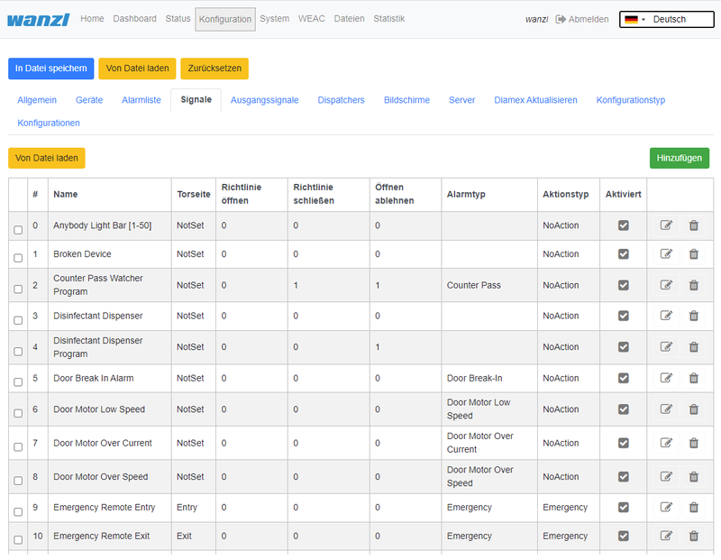
The information in this section is based on FMCU software v2.3.7 and WEAC version 32.14.
[[Datei:FMCU-Signale-en.png|rahmenlos|800x621px]]
==Technischer Hintergrund==
Die Software '''FMCU''' basiert auf einem angepassten UNIX-Betriebssystem, welche unter Anwendung des ]]
===System===
The information in this section is based on FMCU software v2.6.14.
====Network====
[[Datei:FMCU-System-Network-en.png]]
====Hostname====
[[Datei:FMCU-System-Hostname-en.png]]
====Hosts====
[[Datei:FMCU-System-Hosts.en.png]]
====CA Certificates====
[[Datei:FMCU-System-CA-Certificates.en.png]]
====NTP====
[[Datei:FMCU-System-NTP.en.png]]
====nginx====
[[Datei:FMCU-System-nginx.en.png]]
====FMCU====
[[Datei:FMCU-System-FMCU.en.png]]
===Light Schemas===
To navigate the section click "Configuration" -> "Light Schemas". Here you can add and/or customize named color schemes.
[[Datei:configuration-light-schemas-en.png]]
Each schema describes the colors and behaviour of FMCU lights elements like enter and exit zones and the door. Existing light schema you can use in settings of '''Gates''' and '''Alarms'''.
Click Add to create light schema or click "pen" in the table to edit existing schema.
[[Datei:add-light-schema-item-en.png]]
Each light schema is described by the fields below
{| class="wikitable"
|+
!Field
!Description
|-
|Name
|Name of light schema
|-
|Priority
|Priority of using light schema if there is competition situation. Less value means more priority
|-
|Color Entry On
|Color of the gate entry zone during "On" time period
|-
|Color Exit On
|Color of the gate exit zone during "On" time period
|-
|Color Door On
|Color of the doors during "On" time period
|-
|Light Schema On, ms *
|Length of "On" time period in ms
|-
|Light Schema Off, ms *
|Length of "Off" time period in ms
|-
|Color Entry Off
|Color of the gate entry zone during "Off" time period
|-
|Color Exit Off
|Color of the gate exit zone during "Off" time period
|-
|Color Door Off
|Color of the doors during "Off" time period
|-
|Led Image Entry *
|Selected image of the gate entry zone (Arrow, Cross, Empty)
|-
|Led Image Exit *
|Selected image of the gate exit zone (Arrow, Cross, Empty)
|-
|Running Light
|Using "runing light" for the light schema (option)
|}
Click on any field for color to edit color of selected gate element
[[Datei:light-schema-edit-color-rgb-en.png]]
You can select the color space (RGB, HSL, HEX) to set the required color
[[Datei:light-schema-edit-color-hex-en.png]]
===Lights===
To navigate the section click "Configuration" -> "Lights". Here you can add and/or customize light configurations for different gate's modes.
[[Datei:configuration-lights-en.png]]
Each configuration has its own name. The image above shows the default light configuration. Click ''Add'' to create configuration, or "pen" to edit existing one.
[[Datei:editing-light-configuration.png]]
For each mode select existing light schema.
Then you can use the light configuration in "Devices" -> "Gates" settings.
[[Datei:configuration-devices-gates-en.png]]
Press "pen" to edit gate settings, and select light configuration.
[[Datei:gate-light-schema-en.png]]
==Technical Background==
The '''FMCU''' software is based on a customized UNIX operating system, which has been produced using the [https://www.yoctoproject.org/ Yocto-Projektes] produziert worden ist. Es werden nur die benötigten Dienste im Betriebssystem aktiviert. Es werden die für den CPU-Typ optimalen Unterstützungspakete bei der Erstellung des Betriebssystems berücksichtigt. Diese sogenannten Project]. Only the required services are activated in the operating system. The optimal support packages for the CPU type are taken into account when creating the operating system. These so-called '''B'''oard '''S'''upport '''P'''ackages (BSP) werden von den Hardwareherstellern zur Verfügung gestellt und gestatten eine optimale und effiziente Ausnutzung der Hardwareressourcen.
==Funktionen==
Grundsätzlich werden die Funktionen über die Signalverabeitung abgebildet. Die Signale werden durchunterschiedliche Quellen erzeugt. Dazu gehören:
*Lichtleiste
*Lichtsensor
*Deckensensor
*Sonstige
Die Anordnung der Sensoren ist in der nachfolgenden Abbildung dargestellt. In jeder Rahmenhälfte befindet sich eine sogenannte "Inner-Zone" und eine "Outer-Zone". Bei Durchschreiten einer Zutrittskontrolle wird ein Signalflussdiagramm erzeugt, welches für die Abbildung der nachfolgenden Funktionen genutzt wird. [[Datei:image sensors.png|ohne|mini]]Die Lichtleiste dienst als Quelle für mehrere Signale und ist ebenfalls in unterschiedliche Bereiche unterteilt.[[Datei:image lightbar.png|ohne|mini]]In der Standardkonfiguration sind folgende Signale konfiguriert.
{| class="wikitable"
|+
!Signalname
!Rahmenhälfte
|-
|Entry Confirmation
|Eingangare provided by the hardware manufacturers and allow optimal and efficient utilization of the hardware resources.
==Functions==
In principle, the functions are mapped via the signal processing. The signals are generated by different sources including:
*Light bar
*Light sensor
*Ceiling sensor
*Other
The location of the sensors is shown in the figure below. In each half of the frame there is a so-called "inner zone" and an "outer zone". When passing through an access control, a signal flow diagram is generated, which is used to map the following functions.
[[Datei:image_sensors.png]]
The light bar serves as a source for several signals and is also divided into different areas.
[[Datei:image_lightbar.png]]
The following signals are installed in the standard configuration.
{| class="wikitable"
|+
!Signal Name
!Frame Half
|-
|Entry Confirmation
|Entry
|-
|Entry Gate Sensor [U1_E2]
|EingangEntry
|-
|Entry Outer LightBar
|EingangEntry
|-
|Exit Inner LightBar
|EingangEntry
|-
|Free Entry [1000]
|EingangEntry
|-
|Lock Entry [0100]
|EingangEntry
|-
|Open Entry [U1_U2_E3]
|EingangEntry
|-
|Open Entry 70% [U1_E9]
|EingangEntry
|-
|Remote Open Entry
|EingangEntry
|-
|Service Entry [1100]
|EingangEntry
|-
|Emergency Remote
|AusgangExit
|-
|Emergency [U1_U2_E8]
|AusgangExit
|-
|Entry Inner LightBar
|AusgangExit
|-
|Exit Confirmation
|AusgangExit
|-
|Exit Gate Sensor [U2_E5]
|AusgangExit
|-
|Exit Outer LightBar
|AusgangExit
|-
|Free Exit [0010]
|AusgangExit
|-
|Lock Exit [0001]
|AusgangExit
|-
|Open Exit [U1_U2_E4]
|AusgangExit
|-
|Open Exit 70% [U2_E9]
|AusgangExit
|-
|Remote Open Exit
|AusgangExit
|-
|Service Exit [0011]
|Ausgang
|}
===Schliessfahrt mit reduzierter Geschwindigkeit===
Diese Funktion ist für Signale zutreffend, die die Eigenschaft '''CloseGate > 0''' aufweisen. Bei den betroffenen Signalen muss der Wert Exit
|}
===Closing-run at reduced Speed===
This function applies to signals that have the property '''CloseGate > 0'''. For the affected signals, the value '''Close gate speed, % *''' mit einem Wert zwischen 10 und 100% definiert werden. Es besteht somit die Möglichkeit, für unterschiedliche Durchgangszenarien entsprechende Schließgeschwindigkeiten zu definieren. Der Standardwert ist auf 100% festgelegt. In der Standardkonfiguration erfüllen folgende Signale diese Voraussetzungmust be defined with a value between 10 and 100%. It is therefore possible to define appropriate closing speeds for different passage scenarios. The default value is set to 100%. In the standard configuration, the following signals meet this requirement.
{| class="wikitable"
|+
!Signal
!Parameter
!WertValue
|-
|Tailgating watcher
|Close gate speed, % *
|100%
|-
|Entry Gate Sensor [U1_E2]
|Close gate speed, % *
|100%
|-
|Exit Gate Sensor [U2_E5]
|Close gate speed, % *
|100%
|-
|Entry Outer LightBar
|Close gate speed, % *
|100%
|-
|Exit Outer LightBar Exit
|Close gate speed, % *
|100%
|}
===Durchgangsbestätigung===
Diese Funktion setzt einen Impuls mit einer einstellbaren Zeitdauer im Anschlussboard für den Anschluss '''A8'''.Zusätzlich wird erfolgte Durchgang in der Statistik berücksichtigt.
===Koffertrolleyerkennung===
Diese Funktion ist aktiv wenn bei folgenden Signalen die aufgeführten Parameter gesetzt werden. Es bedeutet, dass eine Personen mit einem hinter sich herziehenden Koffer ohne Störung durch vorzeitig schleißende Schwenktüren passieren kann
===Passage Confirmation===
This function sets an impulse with an adjustable duration in the connection board for connection '''A8'''.
===Suitcase Trolley Detection===
This function is active when the listed parameters are set for the following signals. It means that a person with a suitcase being pulled behind them can pass through prematurely closing swing doors without being disturbed.
{| class="wikitable"
|+
!Signal
!Parameter
!WertValue
|-
|Middle Gate Sensor [U1_E1]
|Protect from force close
|true
|-
|Inner LightBar
|Protect from force close
|true
|}
===Mehrfachöffnung===
Diese Funktion ist nur dann gültig, wenn ein Leser für die Eingangsrichtung eingerichtet worden ist. Es bedeutet, dass mehrere Personen in einer Reihe nacheinander den Eingang passieren können, ohne dass die Schwenktür zwischenzeitlich geschlossen wird. Es muss von jeder Person ein Ticket am Kartenleser am Eingang präsentiert werden. Nur bei erfolgreicher Validierung bleiben die Schwenktüren geöffnet. Diese Funktion ist aktiv wenn bei folgenden Signalen die aufgeführten Parameter gesetzt werdenMultiple Opening===
This function is only valid if a reader has been set up for the entry direction. It means that several people can pass through the entrance in a row without the swing door being closed in the meantime. Each person must present a ticket at the card reader at the entrance. The swing doors only remain open if the validation is successful. This function is active when the listed parameters are set for the following signals.
{| class="wikitable"
|+
!Signal
!Parameter
!WertValue
|-
|Middle Gate Sensor [U1_E1]
|Protect from force close
|true
|-
|Inner LightBar
|Protect from force close
|true
|-
|Entry Outer LightBar
|Protect from force close
|true
|-
|Entry Gate Sensor [U1_E2]
|Protect from force close
|true
|-
|Tailgating watcher
|AktiviertActivated
|false
|}
==Tipps zum Arbeiten
==Tips for Working==
[[Datei:image reset-to default.png|rechts|rahmenlos]]Wenn man die Übersicht bei der Konfiguration der Signale verloren hat, kann man über die Funktion
'''Reset to Default'''
einen definierten Ausgangszustand wiederherstellen.{{Box_Hinweis|Hinweis Text = Wenn man die Funktion "Rest to Default" anwendet, gehen die aktuellen Einstellungen verloren. Man kann bei Bedarf vor diesem Schritt die aktuelle Konfiguration exportierenIf you have lost the overview when configuring the signals, you can use the function
'''Reset to Default'''
restore a defined initial state.{{Box_Note|Note Text = If you use the "Rest to Default" function, the current settings will be lost. If necessary, you can export the current configuration before this step.}}{{Links
|
| Thema1 = [[Gate_~_FMCU_Galaxy_Gate_~_user_manual | Galaxy Gate Bedienungsanleitung]]
| Thema2 = [[Gate_~_FMCU_~_management_dashboard | Beschreibung zentrales Dashboard]]
| Thema3 = [[Gate_~_FMCU_~_Inbetriebnahme | Galaxy Gate Inbetriebnahme]]
| Thema4 = [[Gate ~ FMCU ~ Installation Aquado PC (APP Server) | Applikationsserver Zutrittskontrollen]]
| Thema5 = [[Gate ~ FMCU ~ Checkliste | Zutrittskontrollen Checkliste IT Infrastruktur]]
|
}}
[[Kategorie:Galaxy Gate EN]]| (41 dazwischenliegende Versionen von 3 Benutzern werden nicht angezeigt) | |||
| Zeile 3: | Zeile 3: | ||
{{DISPLAYTITLE:Gate ~ FMCU Galaxy Gate ~ User Guide}} | {{DISPLAYTITLE:Gate ~ FMCU Galaxy Gate ~ User Guide}} | ||
| − | == | + | ==Introduction== |
| − | + | The document describes the functions and configuration options of the software '''F'''acility '''M'''anagement '''C'''ontrol '''U'''nit. | |
| − | + | The Facility Management Control Unit is software for access control management. It can be used in an enclosed area such as a sports or entertainment center, an airport zone, universities or security areas. The main components of the software solution are: | |
| − | * | + | *An automated passage control with two-part door and signal lighting |
| − | *Barcode | + | *Barcode (or/and RFID) scanners that read identification data from the customer's ticket or card |
| − | *Tracking | + | *Tracking cameras observing the passage of customers |
| − | * | + | *Info screens showing inbound and outbound information to the customer |
| − | * | + | *One or more external speakers |
| − | * | + | *One or more additional monitors with content tailored to customer needs |
| − | + | The main features are: | |
| − | * | + | *Opening access control upon successful ticket validation |
| − | * | + | *Interaction with customer in response to various events through: |
| − | ** | + | **Light effects |
| − | ** | + | **Voice prompts through internal or external speakers |
| − | ** | + | **Acoustic confirmation of the reading process from barcode scanners |
| − | ** | + | **Visual content displayed on an info screen |
| − | ** | + | **Safe opening and closing of the swing doors by monitoring the passage area |
| − | + | Supported operating modes: | |
*Normal | *Normal | ||
*Service | *Service | ||
| − | * | + | *Fire alarm |
| − | * | + | *Emergency |
| − | + | The variants of Entry Tickets: | |
| − | * | + | *Single entry ticket with closing of access control after passage of one person |
| − | * | + | *Multiple entry ticket with permanent access control |
| − | * | + | *Adjustable time intervals |
| − | * | + | *Consideration of additional conditions about potential-free contacts |
| − | == | + | ==Initial Configuration== |
| − | + | After the software has been downloaded and transferred to the eMMC card according to the documented procedure, see also here [[Gate ~ FMCU ~ Inbetriebnahme|Galaxy Gate Inbetriebnahme/en]], the login screen appears after the first start. After logging in with the user ''Installer'', configuration wizard will be started. | |
| − | + | ===Network=== | |
| − | + | First step is the network settings configuring | |
| − | + | [[Datei:fmcu-configuring-network-en.png]] | |
{| class="wikitable" | {| class="wikitable" | ||
|+ | |+ | ||
!Parameter | !Parameter | ||
| − | ! | + | !Description |
| − | ! | + | !Default Value |
|- | |- | ||
| − | | | + | |Address |
| − | |IP- | + | |IP-Address of access control |
|192.168.1.100 | |192.168.1.100 | ||
|- | |- | ||
| − | | | + | |Mask |
| − | | | + | |Network-Mask |
|255.255.255.0 | |255.255.255.0 | ||
|- | |- | ||
|Gateway | |Gateway | ||
| − | |Gateway- | + | |Gateway-Address |
|192.168.1.1 | |192.168.1.1 | ||
|- | |- | ||
|DNS-Server | |DNS-Server | ||
| − | |DNS-Server | + | |DNS-Server for name resolution |
|192.168.1.1 | |192.168.1.1 | ||
| − | |}{{ | + | |} |
| + | ===FMCU Configuration=== | ||
| + | Next step is selecting FMCU Configuration | ||
| + | [[Datei:fmcu-configuring-configuration-en.png]] | ||
| + | {{Box_Note|Note Text = The configuration always starts with the "Slave" side of the Galaxy Gate. This selection is preset in the assistant "No Device Slave".}}As a type, you can basically make this selection in the assistant. | ||
{| class="wikitable" | {| class="wikitable" | ||
| − | |+ | + | |+Configuration of the Facility Management Control Unit |
| − | ! | + | !Selection |
| − | ! | + | !Description |
|- | |- | ||
|No Device Slave | |No Device Slave | ||
| − | |Slave Unit ( | + | |Slave Unit (Default Selection) |
|- | |- | ||
|Galaxy Gate (Modbus Serial) | |Galaxy Gate (Modbus Serial) | ||
| Zeile 78: | Zeile 82: | ||
|- | |- | ||
|Galaxy Gate (Modbus TCP) | |Galaxy Gate (Modbus TCP) | ||
| − | |Master-Unit | + | |Master-Unit with network connection to Slave-Unit |
|- | |- | ||
|Galaxy Port (Modbus Serial) | |Galaxy Port (Modbus Serial) | ||
| − | |Unit | + | |Unit with serial connection to Slave-Unit |
|- | |- | ||
|Galaxy Port (Modbus TCP) | |Galaxy Port (Modbus TCP) | ||
| − | |Unit | + | |Unit with network connection to Slave-Unit |
|} | |} | ||
{| class="wikitable" | {| class="wikitable" | ||
| − | |+ | + | |+Functions |
| − | ! | + | !Function |
| − | ! | + | !Description |
|- | |- | ||
|AEA | |AEA | ||
| − | | | + | |Configuration for Boarding Gates |
|- | |- | ||
| − | | | + | |Immediate Closure |
| − | | | + | |Closing the swivel arms without swivel range monitoring |
|- | |- | ||
| − | | | + | |Multiple Opening |
| − | | | + | |Swivel arms remain open when multiple input signals are present |
|- | |- | ||
| − | | | + | |Personal Protection |
| − | | | + | |Closing the swivel arms with swivel area monitoring |
|- | |- | ||
| − | | | + | |One-time opening |
| − | | | + | |Single pass even when several input signals are present |
|- | |- | ||
| − | | | + | |Trolley Case |
| − | | | + | |Support of trolley case without alarm |
|- | |- | ||
| − | | | + | |Wheelchair |
| − | | | + | |Assistance from wheelchair without alarm |
| − | |} | + | |}After the function has been selected, the combination of functions results in corresponding configuration types. The function selection is a filter for the resulting configuration type. |
{| class="wikitable" | {| class="wikitable" | ||
| − | |+ | + | |+Configuration type from combination of functions |
| − | ! | + | !Configuration Type |
| − | ! | + | !Description |
|- | |- | ||
|AEA | |AEA | ||
| − | | | + | |Configuration for Boarding Gates |
|- | |- | ||
| − | | | + | |One-time opening Personal Protection |
| − | | | + | |Closing the swivel arms with swivel area monitoring |
|- | |- | ||
| − | | | + | |One-time opening Immediate Closure |
| − | | | + | |Closing the swivel arms without swivel range monitoring |
|- | |- | ||
| − | | | + | |One-time opening Trolley Case |
| − | | | + | |Single passage with trolley case even when several input signals are present |
|- | |- | ||
| − | | | + | |One-time opening Wheelchair |
| − | | | + | |Single passage with a wheelchair even if several input signals are present |
|- | |- | ||
| − | | | + | |Multiple opening personal protection |
| − | | | + | |Closing the swivel arms with swivel area monitoring |
|- | |- | ||
| − | | | + | |Multiple opening instant closure |
| − | | | + | |Closing the swivel arms with swivel area monitoring |
|- | |- | ||
| − | | | + | |Multi-opening trolley case |
| − | | | + | |Swivel arms remain open when several people with wheeled suitcases pass through |
|- | |- | ||
| − | | | + | |Multiple opening wheelchair |
| − | | | + | |Swivel arms remain open when several people with wheeled suitcases pass through |
| − | |} | + | |}After choosing from the three lists, click on '''Apply''', the application will be restarted, you have to wait for the start-up process to be completed. After logging in again, this screen appears.{{Box_Note|Note Text = If you adjust the IP address in the configuration, you must also align the URL in the browser to the new IP address.}} |
| − | + | ===Meta information=== | |
| − | == | + | Next step is filling meta information about FMCU |
| − | + | [[Datei:fmcu-configuring-meta-information-en.png]] | |
| − | + | ||
| − | + | After the input fields have been filled in, you can click on '''Next''' to reach the next page of the wizard. | |
| − | + | ||
| + | ===Configuration of Gate=== | ||
| + | [[Datei:fmcu-configuring-configuration-of-gate-en.png]] | ||
| + | |||
| + | ===WEAC Firmware Update=== | ||
| + | The current WEAC firmware is displayed on the next page of the wizard. If necessary, you can down or upgrade the firmware. | ||
| + | |||
| + | [[Datei:fmcu-configuring-weac-update-en.png]] | ||
| + | |||
| + | The firmware version for each unit is listed as a label next to the activation button. The navigation options are deactivated during the update process. The update process takes about 3 minutes for both units. | ||
| − | + | [[Datei:image_assistant_04a.png]] | |
| + | |||
| + | After checking the WEAC firmware, the swing doors are configured. It is automatically checked whether the minimum requirements regarding the firmware are met. You will be informed on the surface if the firmware has to be updated first. | ||
| + | |||
| + | |||
| + | ===WEAC Doors Update=== | ||
| + | |||
| + | [[Datei:fmcu-configuring-weac-doors-update-en.png]] | ||
| + | |||
| + | If the requirements are met, you can select the swing doors and apply them to the gate. | ||
| + | |||
| + | [[Datei:image_assistant_step06.png]] | ||
| + | |||
| + | ===Configuring the Led Player=== | ||
| + | The next step is to configure the LED player for both units (Master and Slave) accomplished. If necessary, you can adjust the parameters. If the status is '''ready for use''', no modifications are necessary. | ||
| + | |||
| + | [[Datei:fmcu-configuring-led-player-master-en.png]] | ||
| + | |||
| + | The current firmware of the LED player is shown again on the last page of the assistant. Optionally, you can end the configuration with a restart. However, this is only necessary if IP addresses or interface information have changed. | ||
| + | |||
| + | [[Datei:image_assistant_Step08.png]] | ||
| + | |||
| + | After clicking '''Finish''' you can log in again as certain user and work with the Galaxy Gate. If you log in again as user ''installer'', you get a graphical overview, can find out about the status of the access control and can carry out updates if necessary. | ||
| + | So you complete the setup of the access control. | ||
| + | |||
| + | [[Datei:image_status_en.png]] | ||
| + | |||
| + | You can now log in with a service account and carry out further tests. | ||
| + | ==Operation Manual== | ||
| + | ===Configuration of the Swing Doors=== | ||
| + | The swing doors can have different dimensions. Depending on the width and height, this results in other target parameters for optimal curve passage. | ||
| + | [[Datei:image_glasdoors.png]] | ||
| + | |||
| + | After a type has been selected, all parameters can be adjusted according to the needs in the interface before they are then activated via the button '''Apply''' in the configuration on the access control. If you change individual values in the display, the settings must first be saved. To do this, click on the diskette symbol on the left of the interface above the file list. | ||
| + | |||
| + | [[Datei:image_door_settings.png]] | ||
| + | |||
| + | After the changes have been saved, you can activate them using the Apply button. | ||
| + | |||
| + | ===Configuration of the XOVIS Sensors=== | ||
| + | '''Add XOVIS-Sensor''' | ||
| + | |||
| + | Navigate to "Configuration" -> "Devices" -> "Xovis Cameras" and then click on the "Add" button | ||
| + | |||
| + | [[Datei:add_xovis_device_1.png]] | ||
| + | |||
| + | The following fields are filled in the order shown: | ||
#Name | #Name | ||
#URL | #URL | ||
| − | # | + | #Username |
| − | # | + | #Password |
| + | |||
| + | [[Datei:add_xovis_device_2.png]] | ||
| + | |||
| + | The configuration is saved by clicking the '''Save''' button.{{Box_Note|Note Text = After adding the XOVIS sensor, the '''FMCU''' must be restarted before proceeding with the configuration.}}'''Add XOVIS monitoring area as alarm signal''' | ||
| + | |||
| + | Navigate to "Configuration" -> "Signals" and then click on the "Add" button | ||
| + | |||
| + | [[Datei:add_xovis_alarm_signal_1.png]] | ||
| + | |||
| + | The following fields must be filled in here: | ||
| + | |||
| + | #Select type "XOVIS Sensor" | ||
| + | #Specify the name of the signal (e.g. "XOVIS ALARM") | ||
| + | #Set the minimum number of people in the alarm zone to trigger an alarm (e.g. 2) | ||
| + | #Select the alert type (e.g. "Unauthorized Access") | ||
| + | #Determine a list of alarm zones (e.g. "AlarmZone") | ||
| + | #Select the XOVIS sensor added to. | ||
| + | |||
| + | The configuration is saved by clicking the '''Save''' button. | ||
| + | |||
| + | [[Datei:add_xovis_alarm_signal_2.png]] | ||
| + | |||
| + | '''Add XOVIS counter''' | ||
| − | + | Navigate to "Configuration" -> "Signals" and then click on the "Add" button | |
| − | + | [[Datei:add_xovis_alarm_signal_1.png]] | |
| − | + | The following fields must be filled in here: | |
| − | |||
| − | |||
| − | |||
| − | |||
| − | |||
| − | + | #Select type "XOVIS Sensor". | |
| + | #Specify the name of the signal (e.g. "XOVIS Counter") | ||
| + | #Specify the side of the gate (e.g. "Entrance") | ||
| + | #Set the value "Counter". | ||
| + | #Specify a list of lines(e.g. "EntryLine") | ||
| + | #Select the XOVIS camera that you added earlier. | ||
| − | + | The configuration is saved by clicking the '''Save''' button. | |
| − | + | [[Datei:add_xovis_counter_signal.png]] | |
| − | |||
| − | |||
| − | |||
| − | |||
| − | |||
| − | + | ===Store VPN key=== | |
| − | ===VPN | + | A VPN key is required to use remote maintenance. This key can be requested from maxcrc support (support@maxcrc.de) by specifying the project name (Configuration->General view). |
| − | |||
| − | + | After the key file (*.opvn.conf) is available, you can import via the System->OpenVPN page. The following steps are necessary for this. | |
| − | + | Navigating to the '''System-OpenVPN''' page. | |
| − | === | + | |
| − | + | [[Datei:image_openvpn_step01.png]][[Datei:image_openvpn_step02.png]] | |
| − | === | + | |
| − | + | This file is now specified via the '''Select file''' button in the file selection dialog. Then click on '''Upload'''. When the process has been successfully completed, an info icon will appear next to the start button. This means the file has been uploaded successfully, the OpenVPN client can now be activated by clicking on '''Start'''. | |
| − | === | + | |
| + | [[Datei:image_openvpn_step03.png]] | ||
| + | |||
| + | If the start was successful, the color changes from green to red and the label from start to stop. The status of the OpenVPN client and the IP address for access in the VPN network for this gate are displayed to the right of the info symbol. You can disable remote access by clicking the '''Stop''' button. | ||
| + | |||
| + | ===Update Software=== | ||
| + | If there is no Internet connection, individual package installations can be carried out using the '''System->Update software''' menu. You should have a zip archive with the packages to be installed. It must be ensured that no relative paths are used in the archive. Then you can insert the archive into the input line via '''Select file''' and start the update procedure with '''Upload'''. The progress of update process is displayed: | ||
| + | [[Datei:image_software_update.png]][[Datei:image_update_01.png|375x375px]] | ||
| + | |||
| + | If necessary, the application can be restarted. | ||
| + | |||
| + | ===Customer Role=== | ||
| + | When you log in as user ''client'', a simplified interface appears with "Home", "Status", "Statistics" configuration menus. | ||
| + | [[Datei:image_customer_view_en.png]] | ||
| + | |||
| + | In this view you can administrate the access control, but you cannot make any configuration adjustments. The current statistics are displayed directly on the interface, a complete overview of the accesses can be viewed in the '''Statistics''' tab and exported if required. The current status of the individual access control components can be viewed in the '''Status''' tab. The '''Clearance''' option disables all alarms to make the cleaning staff's job easier. The '''Emergency''' option supports the user in opening the access control immediately. | ||
| + | |||
| + | ===Standard Assignment Connection Board=== | ||
'''Unit 1''' | '''Unit 1''' | ||
{| class="wikitable" | {| class="wikitable" | ||
|+ | |+ | ||
| − | ! | + | !Port |
| − | ! | + | !Function |
| − | ! | + | !Description |
|- | |- | ||
|'''LSU (E1)''' | |'''LSU (E1)''' | ||
|LS Middle | |LS Middle | ||
| − | '' | + | ''Center Light barrier'' |
|NO | |NO | ||
| − | '' | + | ''Normally Open Contact'' |
|- | |- | ||
|'''LSV (E2)''' | |'''LSV (E2)''' | ||
|LS Entry | |LS Entry | ||
| − | '' | + | ''Photocell Input'' |
|NO | |NO | ||
| − | '' | + | ''normally open contact'' |
|- | |- | ||
|'''E3''' | |'''E3''' | ||
|Open Entry | |Open Entry | ||
| − | '' | + | ''Single free entry direction Impuls 0,1-1,0 Sek.'' |
|NO | |NO | ||
| − | '' | + | ''Normally Open Contact'' |
|- | |- | ||
|'''E4''' | |'''E4''' | ||
|Open Exit | |Open Exit | ||
| − | '' | + | ''Single free exit direction Impuls 0,1-1,0 Sek.'' |
|NO | |NO | ||
| − | '' | + | ''normally open contact'' |
|- | |- | ||
|'''LSH (E5)''' | |'''LSH (E5)''' | ||
|NA | |NA | ||
| − | '' | + | ''not connected'' |
| | | | ||
|- | |- | ||
|'''E6''' | |'''E6''' | ||
|State bit 0 | |State bit 0 | ||
| − | '' | + | ''Status bit 0'' |
|NO | |NO | ||
| − | '' | + | ''normally open contact'' |
|- | |- | ||
|'''E7''' | |'''E7''' | ||
|State bit 1 | |State bit 1 | ||
| − | '' | + | ''Status bit 1'' |
|NO | |NO | ||
| − | '' | + | ''normally open contact'' |
|- | |- | ||
|'''E8''' | |'''E8''' | ||
|Fire Alarm | |Fire Alarm | ||
| − | '' | + | ''fire alarm system (BMA)'' |
|NC | |NC | ||
| − | '' | + | ''normally closed contact'' |
|- | |- | ||
|'''E9''' | |'''E9''' | ||
|Open Entry 70% | |Open Entry 70% | ||
| − | ''Einzelfrei 70% | + | ''Einzelfrei 70% Input Direction Impuls 0,1-1,0 Sek.'' |
|NO | |NO | ||
| − | '' | + | ''normally open contact'' |
|- | |- | ||
|'''E10''' | |'''E10''' | ||
|Emergency Open Button | |Emergency Open Button | ||
| − | '' | + | ''emergency button'' |
|NC | |NC | ||
| − | '' | + | ''normally closed contact'' |
|- | |- | ||
|'''A8''' | |'''A8''' | ||
|Entry Confirmation | |Entry Confirmation | ||
| − | '' | + | ''Confirmation of passage entry direction Impuls 0,5 Sek.'' |
| +12 VDC | | +12 VDC | ||
|- | |- | ||
|'''A9''' | |'''A9''' | ||
|Exit Confirmation | |Exit Confirmation | ||
| − | '' | + | ''Confirmation of passage exit direction Impuls 0,5 Sek.'' |
| +12 VDC | | +12 VDC | ||
|}'''Unit 2''' | |}'''Unit 2''' | ||
{| class="wikitable" | {| class="wikitable" | ||
|+ | |+ | ||
| − | ! | + | !Port |
| − | ! | + | !Function |
| − | ! | + | !Description |
|- | |- | ||
|'''LSU (E1)''' | |'''LSU (E1)''' | ||
|NA | |NA | ||
| − | '' | + | ''not connected'' |
| | | | ||
|- | |- | ||
|'''LSV (E2)''' | |'''LSV (E2)''' | ||
|NA | |NA | ||
| − | '' | + | ''not connected'' |
| | | | ||
|- | |- | ||
|'''E3''' | |'''E3''' | ||
|Open Entry | |Open Entry | ||
| − | '' | + | ''Single free entry direction Impuls 0,1-1,0 Sek.'' |
|NO | |NO | ||
| − | '' | + | ''normally open contact'' |
|- | |- | ||
|'''E4''' | |'''E4''' | ||
|Open Exit | |Open Exit | ||
| − | '' | + | ''Single free exit direction Impuls 0,1-1,0 Sek.'' |
|NO | |NO | ||
| − | '' | + | ''normally open contact'' |
|- | |- | ||
|'''LSH (E5)''' | |'''LSH (E5)''' | ||
|LS Exit | |LS Exit | ||
| − | '' | + | ''Photocell exit'' |
|NO | |NO | ||
| − | '' | + | ''normally open contact'' |
|- | |- | ||
|'''E6''' | |'''E6''' | ||
|State bit 2 | |State bit 2 | ||
| − | '' | + | ''Status bit 2'' |
|NO | |NO | ||
| − | '' | + | ''normally open contact'' |
|- | |- | ||
|'''E7''' | |'''E7''' | ||
|State bit 3 | |State bit 3 | ||
| − | '' | + | ''status bit 3'' |
|NO | |NO | ||
| − | '' | + | ''normally open contact'' |
|- | |- | ||
|'''E8''' | |'''E8''' | ||
|Fire Alarm | |Fire Alarm | ||
| − | '' | + | ''fire alarm system (BMA)'' |
|NC | |NC | ||
| − | '' | + | ''normally closed contact'' |
|- | |- | ||
|'''E9''' | |'''E9''' | ||
|Open Exit 70% | |Open Exit 70% | ||
| − | '' | + | ''single free 70% exit direction Impuls 0,1-1,0 Sek.'' |
|NO | |NO | ||
| − | '' | + | ''normally open contact'' |
|- | |- | ||
|'''E10''' | |'''E10''' | ||
|Emergency Open Button | |Emergency Open Button | ||
| − | '' | + | ''emergency button'' |
|NC | |NC | ||
| − | '' | + | ''normally closed contact'' |
|- | |- | ||
|'''A8''' | |'''A8''' | ||
| Zeile 339: | Zeile 432: | ||
|'''A9''' | |'''A9''' | ||
|Gate State Error | |Gate State Error | ||
| − | '' | + | ''error condition Durchgang'' |
| +12 VDC | | +12 VDC | ||
| − | |}'''Status | + | |}'''Status Bits''' |
{| class="wikitable" | {| class="wikitable" | ||
|+ | |+ | ||
| − | ! | + | !Status |
!Unit 1 E6 | !Unit 1 E6 | ||
Bit 0 | Bit 0 | ||
| Zeile 362: | Zeile 455: | ||
|- | |- | ||
|Free Entry | |Free Entry | ||
| − | '' | + | ''Entrance permanently free'' |
!'''1''' | !'''1''' | ||
!'''0''' | !'''0''' | ||
| Zeile 369: | Zeile 462: | ||
|- | |- | ||
|Lock Entry | |Lock Entry | ||
| − | '' | + | ''entrance blocked'' |
!'''0''' | !'''0''' | ||
!'''1''' | !'''1''' | ||
| Zeile 376: | Zeile 469: | ||
|- | |- | ||
|Service Entry | |Service Entry | ||
| − | '' | + | ''Permanently open entry direction'' |
!'''1''' | !'''1''' | ||
!'''1''' | !'''1''' | ||
| Zeile 383: | Zeile 476: | ||
|- | |- | ||
|Free Exit | |Free Exit | ||
| − | '' | + | ''Exit permanently free'' |
!'''0''' | !'''0''' | ||
!'''0''' | !'''0''' | ||
| Zeile 390: | Zeile 483: | ||
|- | |- | ||
|Free Entry/Exit | |Free Entry/Exit | ||
| − | '' | + | ''Input/Output permanently free('''Not implemented''')'' |
!'''1''' | !'''1''' | ||
!'''0''' | !'''0''' | ||
| Zeile 397: | Zeile 490: | ||
|- | |- | ||
|Lock Entry / Free Exit | |Lock Entry / Free Exit | ||
| − | '' | + | ''Entrance blocked / exit permanently free'' |
!'''0''' | !'''0''' | ||
!'''1''' | !'''1''' | ||
| Zeile 410: | Zeile 503: | ||
|- | |- | ||
|Lock Exit | |Lock Exit | ||
| − | '' | + | ''exit blocked'' |
!'''0''' | !'''0''' | ||
!'''0''' | !'''0''' | ||
| Zeile 417: | Zeile 510: | ||
|- | |- | ||
|Free Entry / Lock Exit | |Free Entry / Lock Exit | ||
| − | '' | + | ''Entrance permanently free / exit blocked'' |
!'''1''' | !'''1''' | ||
!'''0''' | !'''0''' | ||
| Zeile 437: | Zeile 530: | ||
|- | |- | ||
|Service Exit | |Service Exit | ||
| − | '' | + | ''Permanently open exit direction'' |
!'''0''' | !'''0''' | ||
!'''0''' | !'''0''' | ||
| Zeile 456: | Zeile 549: | ||
|- | |- | ||
|Self Test | |Self Test | ||
| − | '' | + | ''self test'' |
!'''1''' | !'''1''' | ||
!'''1''' | !'''1''' | ||
| Zeile 462: | Zeile 555: | ||
!'''1''' | !'''1''' | ||
|} | |} | ||
| − | === | + | |
| − | + | ===Alarms Definition=== | |
| + | An alarm is triggered as a follow-up action from signals or other sources (e.g. devices). Navigate to "Configuration" -> "Alarms". | ||
| + | |||
| + | [[Datei:configuration-alarms-en.png]] | ||
| + | |||
| + | To create the alarm click on the "Add" button: | ||
| + | |||
| + | [[Datei:add-alarm-en.png]] | ||
| + | |||
| + | An alarm has several general characteristics: Name, Enabled Status, Priority, Sounds settings, Light settings, etc. | ||
| + | |||
| + | In the table below there are descriptions of existing alarms. | ||
| + | |||
{| class="wikitable" | {| class="wikitable" | ||
|+ | |+ | ||
!Definition | !Definition | ||
| − | ! | + | !Description |
| − | ! | + | !Status |
|- | |- | ||
|Connection Alive | |Connection Alive | ||
| − | | | + | |monitors connection to external application |
| − | | | + | |on/off |
|- | |- | ||
|Connection Lost | |Connection Lost | ||
| − | | | + | |monitors connection to external application |
| − | | | + | |on/off |
|- | |- | ||
|Counter Pass | |Counter Pass | ||
| − | | | + | |is set by anti-rotation protection is activated |
| − | | | + | |on/off |
|- | |- | ||
|Door Break-In | |Door Break-In | ||
| − | | | + | |Door is forcibly moved when closed |
| − | | | + | |on/off |
|- | |- | ||
|Emergency | |Emergency | ||
| − | | | + | |is set if the signals on unit 1 E8 or unit 2 E8 are not active (opener). |
| − | | | + | |on/off |
|- | |- | ||
|Fire Alarm | |Fire Alarm | ||
| − | | | + | |is set if the signals on unit 1 E10 or unit 2 E10 are not active (opener). |
| − | | | + | |on/off |
|- | |- | ||
|Invalid Ticket | |Invalid Ticket | ||
| − | | | + | |is set if ticket validation fails |
|Impuls | |Impuls | ||
|- | |- | ||
|Motionless Object | |Motionless Object | ||
| − | | | + | |is set when an object is in the gate area for more than a defined period of time and closing is prevented by a timeout. |
| − | | | + | |on/off |
|- | |- | ||
|No Alarm | |No Alarm | ||
| − | | | + | |is set if no alarm is defined for signals |
| − | | | + | |on/off |
|- | |- | ||
|Proceed Alarm | |Proceed Alarm | ||
| − | | | + | |analogous to Motionless Object with a different time span and other actions without light indication |
| − | | | + | |on/off |
|- | |- | ||
|Server Alarm | |Server Alarm | ||
| − | | | + | |is triggered in the FMCU server |
| − | | | + | |on/off |
|- | |- | ||
|Tailgating | |Tailgating | ||
| − | | | + | |is set if more than one person is in the gate area |
| − | | | + | |on/off |
|- | |- | ||
|Unauthorized Access | |Unauthorized Access | ||
| − | | | + | |is set if a person is in the gate area when the gate is closed |
| − | | | + | |on/off |
|- | |- | ||
|Valid Ticket | |Valid Ticket | ||
| − | | | + | |is set if the ticket validation was successful (trigger beep) |
|Impuls | |Impuls | ||
|} | |} | ||
| − | |||
| − | |||
| − | [[Datei:FMCU-Signale.png | + | ===Signals=== |
| − | == | + | The information in this section is based on FMCU software v2.3.7 and WEAC version 32.14. |
| − | + | ||
| − | = | + | [[Datei:FMCU-Signale-en.png]] |
| − | + | ||
| + | ===System=== | ||
| + | The information in this section is based on FMCU software v2.6.14. | ||
| + | |||
| + | ====Network==== | ||
| + | |||
| + | [[Datei:FMCU-System-Network-en.png]] | ||
| + | |||
| + | ====Hostname==== | ||
| + | |||
| + | [[Datei:FMCU-System-Hostname-en.png]] | ||
| + | |||
| + | ====Hosts==== | ||
| + | |||
| + | [[Datei:FMCU-System-Hosts.en.png]] | ||
| + | |||
| + | |||
| + | ====CA Certificates==== | ||
| + | |||
| + | [[Datei:FMCU-System-CA-Certificates.en.png]] | ||
| + | |||
| + | ====NTP==== | ||
| + | |||
| + | [[Datei:FMCU-System-NTP.en.png]] | ||
| + | |||
| + | |||
| + | ====nginx==== | ||
| + | |||
| + | [[Datei:FMCU-System-nginx.en.png]] | ||
| + | |||
| + | |||
| + | ====FMCU==== | ||
| + | |||
| + | [[Datei:FMCU-System-FMCU.en.png]] | ||
| + | |||
| + | ===Light Schemas=== | ||
| + | |||
| + | To navigate the section click "Configuration" -> "Light Schemas". Here you can add and/or customize named color schemes. | ||
| + | |||
| + | [[Datei:configuration-light-schemas-en.png]] | ||
| + | |||
| + | Each schema describes the colors and behaviour of FMCU lights elements like enter and exit zones and the door. Existing light schema you can use in settings of '''Gates''' and '''Alarms'''. | ||
| + | |||
| + | Click Add to create light schema or click "pen" in the table to edit existing schema. | ||
| + | |||
| + | [[Datei:add-light-schema-item-en.png]] | ||
| + | |||
| + | Each light schema is described by the fields below | ||
| + | |||
| + | {| class="wikitable" | ||
| + | |+ | ||
| + | !Field | ||
| + | !Description | ||
| + | |- | ||
| + | |Name | ||
| + | |Name of light schema | ||
| + | |- | ||
| + | |Priority | ||
| + | |Priority of using light schema if there is competition situation. Less value means more priority | ||
| + | |- | ||
| + | |Color Entry On | ||
| + | |Color of the gate entry zone during "On" time period | ||
| + | |- | ||
| + | |Color Exit On | ||
| + | |Color of the gate exit zone during "On" time period | ||
| + | |- | ||
| + | |Color Door On | ||
| + | |Color of the doors during "On" time period | ||
| + | |- | ||
| + | |Light Schema On, ms * | ||
| + | |Length of "On" time period in ms | ||
| + | |- | ||
| + | |Light Schema Off, ms * | ||
| + | |Length of "Off" time period in ms | ||
| + | |- | ||
| + | |Color Entry Off | ||
| + | |Color of the gate entry zone during "Off" time period | ||
| + | |- | ||
| + | |Color Exit Off | ||
| + | |Color of the gate exit zone during "Off" time period | ||
| + | |- | ||
| + | |Color Door Off | ||
| + | |Color of the doors during "Off" time period | ||
| + | |- | ||
| + | |Led Image Entry * | ||
| + | |Selected image of the gate entry zone (Arrow, Cross, Empty) | ||
| + | |- | ||
| + | |Led Image Exit * | ||
| + | |Selected image of the gate exit zone (Arrow, Cross, Empty) | ||
| + | |- | ||
| + | |Running Light | ||
| + | |Using "runing light" for the light schema (option) | ||
| + | |} | ||
| + | |||
| + | Click on any field for color to edit color of selected gate element | ||
| − | + | [[Datei:light-schema-edit-color-rgb-en.png]] | |
| − | |||
| − | |||
| − | |||
| − | + | You can select the color space (RGB, HSL, HEX) to set the required color | |
| + | |||
| + | [[Datei:light-schema-edit-color-hex-en.png]] | ||
| + | |||
| + | ===Lights=== | ||
| + | |||
| + | To navigate the section click "Configuration" -> "Lights". Here you can add and/or customize light configurations for different gate's modes. | ||
| + | |||
| + | [[Datei:configuration-lights-en.png]] | ||
| + | |||
| + | Each configuration has its own name. The image above shows the default light configuration. Click ''Add'' to create configuration, or "pen" to edit existing one. | ||
| + | |||
| + | [[Datei:editing-light-configuration.png]] | ||
| + | |||
| + | For each mode select existing light schema. | ||
| + | |||
| + | Then you can use the light configuration in "Devices" -> "Gates" settings. | ||
| + | |||
| + | [[Datei:configuration-devices-gates-en.png]] | ||
| + | |||
| + | Press "pen" to edit gate settings, and select light configuration. | ||
| + | |||
| + | [[Datei:gate-light-schema-en.png]] | ||
| + | |||
| + | ==Technical Background== | ||
| + | The '''FMCU''' software is based on a customized UNIX operating system, which has been produced using the [https://www.yoctoproject.org/ Yocto Project]. Only the required services are activated in the operating system. The optimal support packages for the CPU type are taken into account when creating the operating system. These so-called '''B'''oard '''S'''upport '''P'''ackages (BSP) are provided by the hardware manufacturers and allow optimal and efficient utilization of the hardware resources. | ||
| + | |||
| + | ==Functions== | ||
| + | In principle, the functions are mapped via the signal processing. The signals are generated by different sources including: | ||
| + | |||
| + | *Light bar | ||
| + | *Light sensor | ||
| + | *Ceiling sensor | ||
| + | *Other | ||
| + | |||
| + | The location of the sensors is shown in the figure below. In each half of the frame there is a so-called "inner zone" and an "outer zone". When passing through an access control, a signal flow diagram is generated, which is used to map the following functions. | ||
| + | |||
| + | [[Datei:image_sensors.png]] | ||
| + | |||
| + | The light bar serves as a source for several signals and is also divided into different areas. | ||
| + | |||
| + | [[Datei:image_lightbar.png]] | ||
| + | |||
| + | The following signals are installed in the standard configuration. | ||
{| class="wikitable" | {| class="wikitable" | ||
|+ | |+ | ||
| − | ! | + | !Signal Name |
| − | ! | + | !Frame Half |
|- | |- | ||
|Entry Confirmation | |Entry Confirmation | ||
| − | | | + | |Entry |
|- | |- | ||
|Entry Gate Sensor [U1_E2] | |Entry Gate Sensor [U1_E2] | ||
| − | | | + | |Entry |
|- | |- | ||
|Entry Outer LightBar | |Entry Outer LightBar | ||
| − | | | + | |Entry |
|- | |- | ||
|Exit Inner LightBar | |Exit Inner LightBar | ||
| − | | | + | |Entry |
|- | |- | ||
|Free Entry [1000] | |Free Entry [1000] | ||
| − | | | + | |Entry |
|- | |- | ||
|Lock Entry [0100] | |Lock Entry [0100] | ||
| − | | | + | |Entry |
|- | |- | ||
|Open Entry [U1_U2_E3] | |Open Entry [U1_U2_E3] | ||
| − | | | + | |Entry |
|- | |- | ||
|Open Entry 70% [U1_E9] | |Open Entry 70% [U1_E9] | ||
| − | | | + | |Entry |
|- | |- | ||
|Remote Open Entry | |Remote Open Entry | ||
| − | | | + | |Entry |
|- | |- | ||
|Service Entry [1100] | |Service Entry [1100] | ||
| − | | | + | |Entry |
|- | |- | ||
|Emergency Remote | |Emergency Remote | ||
| − | | | + | |Exit |
|- | |- | ||
|Emergency [U1_U2_E8] | |Emergency [U1_U2_E8] | ||
| − | | | + | |Exit |
|- | |- | ||
|Entry Inner LightBar | |Entry Inner LightBar | ||
| − | | | + | |Exit |
|- | |- | ||
|Exit Confirmation | |Exit Confirmation | ||
| − | | | + | |Exit |
|- | |- | ||
|Exit Gate Sensor [U2_E5] | |Exit Gate Sensor [U2_E5] | ||
| − | | | + | |Exit |
|- | |- | ||
|Exit Outer LightBar | |Exit Outer LightBar | ||
| − | | | + | |Exit |
|- | |- | ||
|Free Exit [0010] | |Free Exit [0010] | ||
| − | | | + | |Exit |
|- | |- | ||
|Lock Exit [0001] | |Lock Exit [0001] | ||
| − | | | + | |Exit |
|- | |- | ||
|Open Exit [U1_U2_E4] | |Open Exit [U1_U2_E4] | ||
| − | | | + | |Exit |
|- | |- | ||
|Open Exit 70% [U2_E9] | |Open Exit 70% [U2_E9] | ||
| − | | | + | |Exit |
|- | |- | ||
|Remote Open Exit | |Remote Open Exit | ||
| − | | | + | |Exit |
|- | |- | ||
|Service Exit [0011] | |Service Exit [0011] | ||
| − | | | + | |Exit |
|} | |} | ||
| − | === | + | ===Closing-run at reduced Speed=== |
| − | + | This function applies to signals that have the property '''CloseGate > 0'''. For the affected signals, the value '''Close gate speed, % *''' must be defined with a value between 10 and 100%. It is therefore possible to define appropriate closing speeds for different passage scenarios. The default value is set to 100%. In the standard configuration, the following signals meet this requirement. | |
{| class="wikitable" | {| class="wikitable" | ||
|+ | |+ | ||
!Signal | !Signal | ||
!Parameter | !Parameter | ||
| − | ! | + | !Value |
|- | |- | ||
|Tailgating watcher | |Tailgating watcher | ||
| Zeile 640: | Zeile 877: | ||
|100% | |100% | ||
|} | |} | ||
| − | === | + | |
| − | + | ===Passage Confirmation=== | |
| − | === | + | This function sets an impulse with an adjustable duration in the connection board for connection '''A8'''. |
| − | + | ===Suitcase Trolley Detection=== | |
| + | This function is active when the listed parameters are set for the following signals. It means that a person with a suitcase being pulled behind them can pass through prematurely closing swing doors without being disturbed. | ||
{| class="wikitable" | {| class="wikitable" | ||
|+ | |+ | ||
!Signal | !Signal | ||
!Parameter | !Parameter | ||
| − | ! | + | !Value |
|- | |- | ||
|Middle Gate Sensor [U1_E1] | |Middle Gate Sensor [U1_E1] | ||
| Zeile 658: | Zeile 896: | ||
|true | |true | ||
|} | |} | ||
| − | === | + | ===Multiple Opening=== |
| − | + | This function is only valid if a reader has been set up for the entry direction. It means that several people can pass through the entrance in a row without the swing door being closed in the meantime. Each person must present a ticket at the card reader at the entrance. The swing doors only remain open if the validation is successful. This function is active when the listed parameters are set for the following signals. | |
{| class="wikitable" | {| class="wikitable" | ||
|+ | |+ | ||
!Signal | !Signal | ||
!Parameter | !Parameter | ||
| − | ! | + | !Value |
|- | |- | ||
|Middle Gate Sensor [U1_E1] | |Middle Gate Sensor [U1_E1] | ||
| Zeile 683: | Zeile 921: | ||
|- | |- | ||
|Tailgating watcher | |Tailgating watcher | ||
| − | | | + | |Activated |
|false | |false | ||
|} | |} | ||
| − | == | + | |
| − | [[Datei:image reset-to default.png|rechts|rahmenlos]] | + | ==Tips for Working== |
| + | [[Datei:image reset-to default.png|rechts|rahmenlos]]If you have lost the overview when configuring the signals, you can use the function | ||
'''Reset to Default''' | '''Reset to Default''' | ||
| − | + | restore a defined initial state.{{Box_Note|Note Text = If you use the "Rest to Default" function, the current settings will be lost. If necessary, you can export the current configuration before this step.}}{{Links | |
| | | | ||
| Thema1 = [[Gate_~_FMCU_Galaxy_Gate_~_user_manual | Galaxy Gate Bedienungsanleitung]] | | Thema1 = [[Gate_~_FMCU_Galaxy_Gate_~_user_manual | Galaxy Gate Bedienungsanleitung]] | ||
