Gate ~ Installation
Inhaltsverzeichnis
Preparation
The commissioning of the Galaxy Gate is started by providing an image. The network configuration is prepared with a static IP address. The external camera XOVIS is also equipped with a static IP address.
| Device | IP address |
| Odroid IP | 192.168.1.100 |
| Xovis IP | 192.168.1.168 |
These initial parameters are part of the image. All further steps are based on this configuration of the IP addresses.
The image is provided in the form of a file from maxcrc via a specified download URL. maxcrc updates the image in case of software changes such as bug fixes or the support of new hardware components. It must always be checked in advance whether the current image exists in the download area. Current sources are listed below.
| Image | Link |
| FMCU | 1.7.4 |
| WEAC | 30.21 |
| Diamex | 1.3.0 |
| WENI | 0.0.1 |
This file is now extracted and copied to the eMMC card using a software tool. This process can be performed on any Windows computer that has a card reader with a micro SD slot.
The image is now transferred to the SD card using the "Win32DiskImager" tool. The tool can be downloaded here:
After launching the program, select the previously extracted image file. The device letter is the drive assigned to the SD card on the PC. Make sure the eMMC adapter and eMMC card are properly inserted before clicking the button. You must confirm the writing before the process begins. After writing, you need to click on the "Verify" button to ensure that the written data has been transferred to the eMMC card without errors.
The final step is to insert the prepared eMMC card into the ODROID single-board computer.
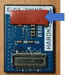
Remove the protective film of the double-sided tape:
Align the eMMC module and the eMMC connector flush on the ODROID-C2 board using the white rectangle on the board as a guide.
Slowly push in the eMMC until the card clicks into place.
Now the single-board computer is connected to a computer via a network cable. After switching on the power supply of the access control, the configuration can be continued with an Internet browser (e.g. Chrome).
USB-Pinout ODROID
The pin assignment of the single-board computer is shown in the following illustration.
| Connection | Description |
|---|---|
| USB1 | |
| USB2 | RS232-Adapter for DUOmetrics |
| USB3 | LED-Controller for LED-Matrix and LED-Lightband |
| USB4 | USB-RS485 nano Adapter for WEAC-Board |
Technical Information
Configuration
The IP address is entered in the browser's URL bar. http://192.168.1.100
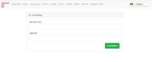
The following login window appears
The following login information is stored:
| Username | Password |
|---|---|
| wanzl | wanzlfmcu! |
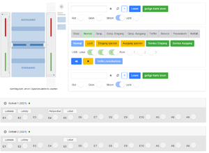
After successful login, this view appears.
In this representation you can already read different information and determine the status of the access control. The left visual representation of the access control describes the current status. If the bracket light is not flashing red, the condition is normal and the connection between FMCU and WEAC has been established successfully. The two LED displays in the horizontal display of unit 1 and unit 2 also indicate the connection status visually. The current version of the WEAC firmware is shown in brackets.
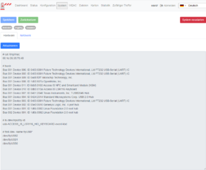
In the event of an error, you must check the address of the USB access. On the system page of the application (http://192.168.1.100/system) all USB ports used are displayed.
In this example, three components are connected.
| Connection | Usage |
|---|---|
| /dev/ttyUSB2 | Components1 |
| /dev/ttyUSB1 | Components2 |
| /dev/ttyUSB0 | Components3 |
The connection to WEAC is always shown with the USB0 or USB1 connections. You can check the current settings by looking at the configuration of the gate (http://192.168.1.100/configuration#gate)
Setting the address of the USB port to the WEAC board is further down this dialog. "Simulator" is set for Gate on the Slave FMCU.
When using a slave FMCU, the IP address is set via the menu (http://192.168.1.100/configuration#slave_fmcu).
Furthermore, the IP address must be entered in the white list under "Authentication and linked gates".
Master-FMCU: 192.168.1.101, Slave-FMCU: 192.168.1.100 When using the light bar, it is also important to ensure that all three sensors are activated.
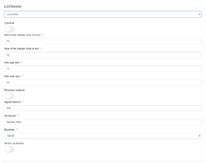
The parameters of the light bar are set via the menu navigation (http://192.168.1.100/configuration#light_bar).
The values listed here can be accepted as standard. Before the light bar can be used, a self-adjustment must be carried out. These steps are explained below.
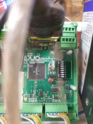
1. There is no supply voltage at the light bar controller. The device is switched off.
2. Monitoring area is free.
3. DIP3 to ON (Evaluation on LVX board)
4. turn on a device.
5. LEDs check:
The green LED D should light up. (evaluation on LVX board)
No blinking or glowing of the red error LEDs.
6. DIP3 back to OFF during operation.
=> The device saves the values in the EEPROM and goes into normal operation. If you do not want to save the setting: Switch off the supply as long as DIP3 is ON.
Notice:
If the device is switched off while the reference values are being saved (before LED "B" flashes), this can lead to unintentional blanking.
LED states during self-adjustment
After all settings have been checked and adjusted if necessary, you can carry out various actions on the dashboard page.
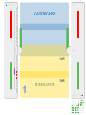
Depending on the action, the following states are displayed graphically in the view (http://192.168.1.100/dashboard).
Test Lightbar
The light bar from the manufacturer Duometrics must first be calibrated with the correct mode. The details can be found in the hardware instructions. After the calibration is complete, the connector board must have these settings.
The correct configuration of the light bar can be checked on the status page (http://192.168.1.100/status) of the application.
If an error occurs in the communication, this error is displayed here accordingly.
After the settings have been checked, the function can be tested by setting the "Permanently free" status in the entry direction. This is done via the configuration of the barcode reader (http://192.168.1.100/configuration#barcode_scanner_entry). There the entry "Light Bar" is selected.
After that, one person can walk through the gate in the direction of entry. This action is represented visually on the dashboard.
This completes the check of the light bar.
Test Lightband
The light band is controlled with the Diamex component. The availability status of this component can be displayed on the page. (http://192.168.1.100/update).
This status is only displayed correctly after configuration of the light band for master and slave.
You have to load the current motifs for the light control onto the module. The file is located here:
As with all other components, the status of the component can be checked on the status page. (http://192.168.1.100/status).
It should be noted that there are two components for the light line control. Each frame has different configuration parameters to consider. Master and slave are always defined.
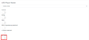
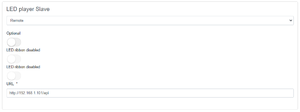
If there is no LED matrix, "No matrix" should be activated.(https://192.168.1.100/configuration#led_player_master)
The light band must behave synchronously on both halves of the frame. For this reason, communication with the slave side is set on the master side.
Display Master FMCU (http://192.168.1.101/api)
Functional Tests
Setting up the System at the Customer
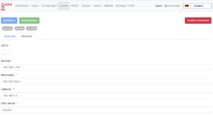
When setting up the system in the customer network, the network configuration must first be adjusted. To do this, you log in with the web browser with the stored login information, as you did during commissioning, after the computer has been connected to the access control system via the network.
Now go to the System page and select the Network tab there. (http://192.168.1.100/system)
Here you enter the network information provided by the customer for IP address, net mask, gateway and DNS server, click on Save and restart the system (Restart system). Then the network cable of the customer network is connected to the system and the other settings can be continued with any PC in the customer network.
Software Building Blocks
The user interface supports the configuration of the access control through standardized processes that are summarized in the form of so-called software modules. The individual setting options are listed below. The various settings are bundled into categories and are based on similar movement sequences.
Standard I (horizontal lightbar)
| Function | Description | Standard |
|---|---|---|
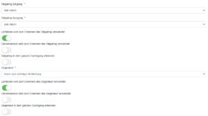
| Tailgating Entry | Access control is configured for single pass. The passage is checked by presenting the ticket at the card reader. If, after passing a successful test, a second person uses the passage without a test, an alarm with visual and audible alarm is triggered. The access control can either react as follows. The closing process is started immediately, regardless of people in the pivoting area. The closing process only starts when nobody is in the pivoting area.
This results in the following options: - no Alarm - Alarm - Alarm and closing after leaving the swivel range - Alarm and close immediately |
no Alarm |
| Tailgating Exit | The description is analogous to the "Tailgating input" function | no Alarm |
| Light bar is used to detect Tailgating | If this switch is activated, the light bar is used for person detection. | activated |
| Ceiling sensor is used to detect tailgating | If this switch is activated, the ceiling sensor is used for people detection. | not activated |
| Detect tailgating throughout the run | This function can only be used when using the ceiling sensor. The area in front of the glass bracket is divided into two zones. There is an "outer zone" and an "inner zone". If this function is activated, the 2nd person is already recognized in the "outer zone". The alarm can therefore be given at an earlier point in time. | not activated |
| reverse | When using the light bar, identification occurs when entering the frame. When using the camera, this effect can be detected before the frame enters. The following options are possible:
- no Alarm - Alarm - Alarm and closing after leaving the swivel range - Alarm and close immediately |
no Alarm |
| Light bar is used to detect reverse rotation | When this switch is activated, the light bar is used as a sensor. | activated |
| Ceiling sensor is used to detect counter-rotation | If this switch is activated, the ceiling sensor is used as a sensor. | not activated |
| Detect reverse flow throughout the passage | This function can only be used when using the ceiling sensor. The area in front of the glass bracket is divided into two zones. There is an "outer zone" and an "inner zone". If this function is activated, the 2nd person is already recognized in the "outer zone". The alarm can therefore be given at an earlier point in time. | not activated |
Standard II (vertical light bar and horizontal light bar)
| Function | Description | Standard |
|---|---|---|
| Height definition for entering objects (especially children) | ||
Premium (horizontal and vertical light bar inkl. 1 Ceiling Sensor)
| Function | Description | Standard |
|---|---|---|
| Height definition for entering objects (especially children). person may pass through the gate with a trolley. The swivel arms then close after leaving the swivel range | ||
| Extended tailgating by ceiling sensor (no influence on user interface) | ||
Extended Tailgating by ceiling Sensor (no influence on user interface)
| Function | Description | Standard |
|---|---|---|
| Individual recognition on the card reader, the reading areas may only be entered individually, otherwise the gate will not open. In the event of an attempt at manipulation, the gate closes in any case. | ||
| additional monitoring of areas in the vicinity of the access control | ||
Additional Options
| Function | Description | Standard |
|---|---|---|
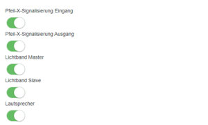
| Arrow-X-Signal Entry | ||
| Arrow-X Signal Exit | ||
| Lightband Master | ||
| Lightband Slave | ||
| Speaker |
Audio-Files
The assignment of the MP3 file names for use can be found in the following table:
| Name | Function |
|---|---|
| MP3_1.mp3 | Beep after a Barcode has been read |
| MP3_2.mp3 | Please go through the Gate |
| MP3_3.mp3 | Random Hit |
| MP3_4.mp3 | Alarm |
| MP3_5.mp3 | Please enter the readers' area individually |
| MP3_6.mp3 | Please leave the readers area |
| MP3_7.mp3 | Emergency |
