People Counter Dashboard
Inhaltsverzeichnis
Prepare KBOX A-330-RPI
Download image
| Version | Download Link |
|---|---|
| 1.3.0.1 | http://nas0.dnsalias.com:5000/sharing/wZzteL0s7 |
Copy image to the Micro SD Card
1. Download an image from the table above
2. Extract an archive
3. Use utility HDDRawCopy1.10Portable from the archive to copy the image on the Micro SD Card
Setup XOVIS cameras
Add XOVIS cameras
1. To add a new XOVIS camera, you firstly need to select the Devices/ Geräte tab.
2. Click on the Add/ Hinzufügen button.
3. Here you should specify the camera URL.
4. Specify a login to access the camera.
5. Specify a password to access the camera.
6. In this field specify the URL of your server (this field will be used for PUSH notification configuration on the camera side).
7. Save it.
Change camera credentials
1. If you want to change camera data just click on the camera list area.
2 Then click on the Edit/ Bearbeiten button.
3. After that you can change camera data.
4. And save changes.
Delete API cameras.
1. To remove unwanted cameras, mark them.
2. Click on the Delete/ Löschen button.
Additional field designations.
The status icon shows the connection to the camera. If it is green then the connection exists, if it is red then no connection exists.
The status connection you can see also if you just click on the camera list area.
This field shows the connection error.
MAC camera address. It is automatically filled in by the server.
Setup Dashboards
Add Dashboard.
1. Add a new dashboard, you firstly need to go to Dashboard.
2. Select the Dashboards tab.
3. And then click on the Add/ Hinzufügen button.
4. Enter here the name of the area.
5. Here you should specify a unique name without spaces and starts with a lowercase letter. This is a service field. For example: If you specified the name "Test", you can specify a unique name "test".
6. Here you can select a theme for the area display. For example:
7. Here you can choose the background for the "Basic" theme. If you want to add an image, you should upload it up to the server. More details on the link upload files
8. This field can be used in case if you want to specify an Offset for counter(for example when people are already in the area, but camera's counter is zero).
9. Click on the Add/ Hinzufügen button to add a camera.
10. Select the camera that was added earlier. If you do not know how to add a camera to click on this link setup XOVIS cameras
11. Choose the detect type.
12. Enter the name line.
13. Here we specify the maximum capacity of the number of people.
14. Here you can specify the schedule restart counter time. If you need to specify more than 2 values, be sure to separate them with a semicolon.
If you need to change the text translation on Dashboard by interval:
15. To add the ability to select a language, click the Add/ Hinzufügen button as many times as you need the languages.
16. Choose a language.
17. Enter the language switching interval in seconds.
18. And save it.
Change Dashboard credentials
1. If you want to change dashboard data just click on the dashboard list area.
2. Then click on the Edit/ Bearbeiten button.
3. After that you can change dashboard data. 4. And save changes.
Delete Dashboard.
1. To remove unwanted Dashboard, mark them.
2. And then click on the Delete/ Löschen button.
Setup Executable Devices
Add Executable Devices
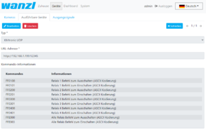
1. To add a new executable device, you firstly need to select the Devices/ Geräte tab.
2. Select the Executable Devices/ Ausführbare Geräte tab.
3. And then click on the Add/ Hinzufügen button.
4. Select the type of executable device communication protocol.
5. Here you should specify the executable device URL.
6. And Save it.
Change Executable Device credentials
1. If you want to change executable device data just click on the executable device list area.
2. Then click on the Edit/ Bearbeiten button.
3. After that you can change executable device data.
4. And save changes.
Delete Executable Device
1. To remove an executable device, mark them.
2. Be careful! Do not remove an executable device that is used. Click on the Delete/ Löschen button.
Additional field designations.
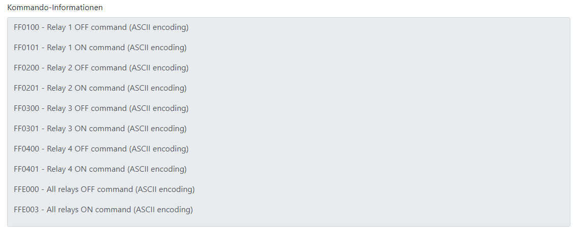
Command Information/ Kommando-Informationen contains information about commands to control the device.
Setup Output Signals of Executable Device
Add Output Signals
1. To add new output signals, you firstly need to select the Devices/ Geräte tab.
2. Select the Output Signals/ Ausgangssignale tab.
3. And then to click on the Add/ Hinzufügen button.
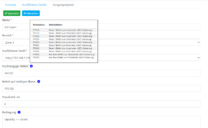
4. Enter here the name of the output signals.
5. Here you should select an area.
6. Here you should choose the executable device URL.
7. Insert the command of a high level of the executable device.
8. Insert the command of a low level of the executable device.
9. Here you can specify transition delay time.
10. This field is necessary to specify the condition of relay triggering.
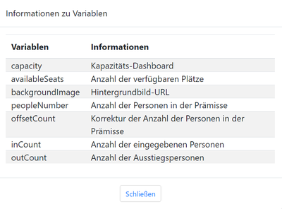
Information about Variables
11. Save it.
Change Output Signals credentials
1. If you want to change output signals data just click on the output signals list area.
2. Then click on the Edit/ Bearbeiten button.
3. After that you can change its data.
4. And save changes.
Delete Output Signals
1. To remove unwanted Output Signals, mark them.
2. Click on the Delete/ Löschen button.
Upload files to the server
Add Files.
1. Add a new area, you firstly need to go to Dashboard.
2. Select the Image Assets/ Bild-Assets tab.
3. And then click on the Add/ Hinzufügen button and select a file on your file system. If a file is uploaded to the server, you can see it in the file list.
Show uploaded image files.
1. If you want to see image files just click on the file list area.
Delete Files.
1. To remove unwanted files on the server, mark them. Preset files can't be deleted.
2. And then click on the Delete/ Löschen button.
Users
Add a user
1. To add a new user, you firstly need to select the System tab.
2. Click on the Users/ Benutzer tab.
3. Then click on the Add/ Hinzufugen button.
4. In this field you should specify Login/ Anmeldung for a new user
5. In this field you should specify Password/ Passwort for a new user
6. If you want to grant the user administrator rights, tip this field. (Administrative rights give rights to edit, create, delete and view. And the standard rights only to view.)
7. Click on the Save/ Speichern button to complete the adding of a new user.
Change user credentials
1. If you want to change user data just click on the user list area.
2. Then click on the Edit/ Bearbeiten button.
3. After that you can change user data. 4. And save the changes.
Remove a user
1. To remove unwanted user, mark them. Preset files can't be deleted.
2. And then click on the Delete/ Löschen button.
Change browser configuration
Reload browser configuration.
1. To display, you firstly need to go to System.
2. Select the Display/ Bildschirm tab.
3. If you need a mouse cursor to be displayed in the kiosk, tip this field.
4. Enter the display URL.
5. Click on the Save button.
6. Then click on the Reboot button.
Network
Network Setup.
1. To configure or view the network settings, you firstly need to go to System.
2. Select the Network tab.
There are two methods of network configuration.
The first method:
- Tip the field.
- Click on the Save button.
- Then click Reboot button. And the DHCP server will automatically give the necessary settings.
The second method:
- Specify an IP address.
- Enter netmask.
- Input address of the gateway.
- Now fill in the DNS IP address.
- And then clock on the *Reload* button.
Example configuration layout with access control unit
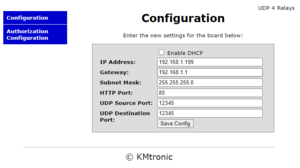
Configure external device ( KMTronic producer homepage)
The default configuration can be reviewed on the homepage of the producer.
There are a total of 4 relays for this external device, each with a normally open / normally closed contact. In the Output signals tab, you can now select a relay that will be used as a switch for access control.
In this configuration, relay 1 is used as a switching contact in the signal definition. A pulse length of 0 ms is defined, which means it is an on / off switch. In this configuration, the switching pulse is set when the actual number of people is greater than the set maximum capacity.
The technical connection overview is shown in this illustration. The signal lines are connected as NO (Normal Open) to contact U2 E7 on the connection board. This means that if the maximum capacity is exceeded, the access control is blocked.
If necessary, several switching contacts can be used according to the technical requirements.
Guides
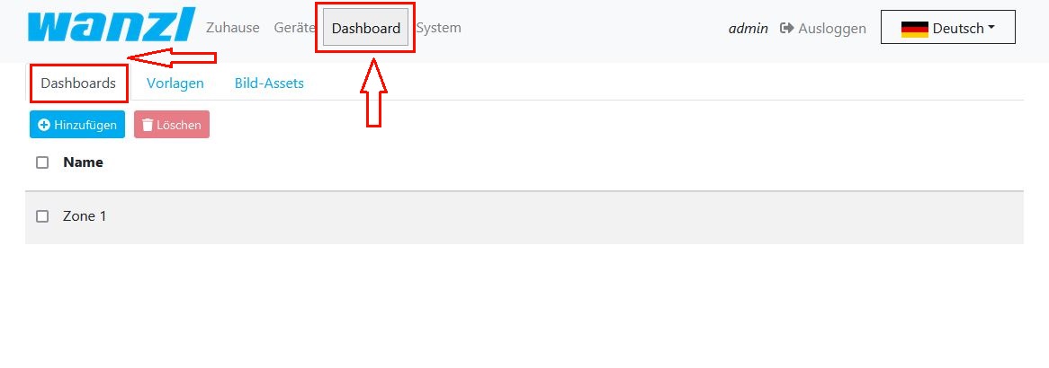
How to change area capacity
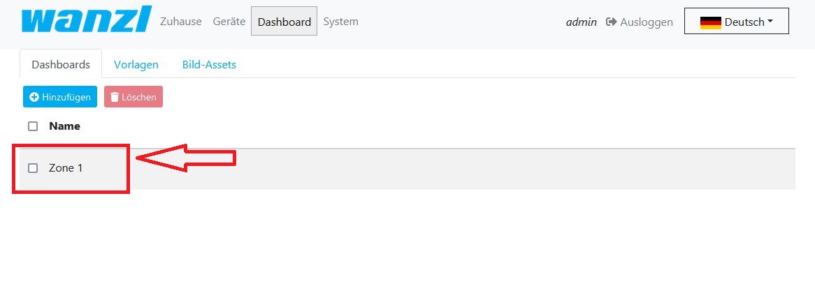
- Open dashboard list
2. Open dashboard which you want to modify
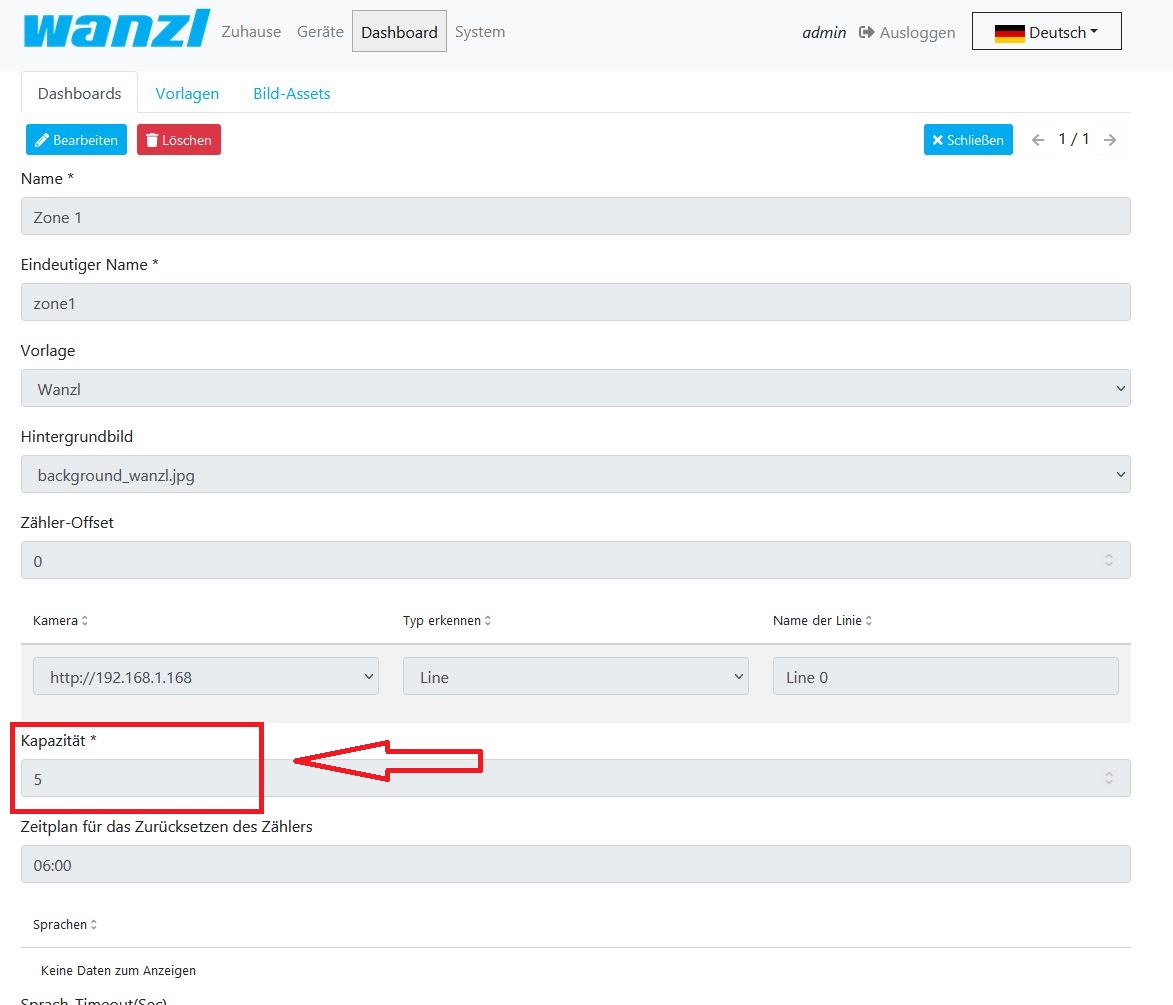
3. Press "Edit" to modify dashboard configuration
4. Find "Capacity" field and enter a value
5. Save changes


