Gate ~ FMCU Galaxy Gate ~ management dashboard
Inhaltsverzeichnis
General
The Wanzl Access Manager offers a central dashbaord for access controls in a homogeneous interface, displays the corresponding states and supports the user in the administration of these components. The Wanzl Access Manager is a leading platform for monitoring and managing access controls of security areas.
Headline
| Nummer | Funktion |
|---|---|
| 1 | Button Management Dashboard |
| 2 | Administration |
| 3 | Events Button |
| 4 | Cards Button |
| 5 | Statistics Button |
| 6 | Logged in User |
| 7 | Log out Button |
| 8 | Languages menu |
| 9 | Adjust the display to entire width of the screen |
Menu items
Gates
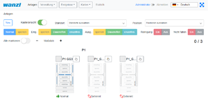
https://<dns-name or ip-address>/gatesIn dieser Ansicht werden alle Zutrittskontrollen in einer intuitiven Oberfläche dargestellt. Es existieren Gruppierungsmöglichkeiten in zwei Kategorien. Zunächst kann man nach Standort gruppieren. Innerhalb des Standortes kann man dann verschiedene Lokationen zusammenfassen. Einzelne Gates können über den Menüpunkt "Neu" hinzugefügt werden.
Set up a new Gate
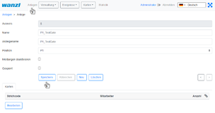
In dieser Ansicht legen Sie ein neues Gate an. Die Felder Namen, Anzeigename und Position des Gates müssen mit Werten belegt werden. Danach auf Anlagen klicken.
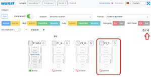
Sie sehen nun in der Ansicht das Sie ein NEUES Gate angelegt haben,
in diesem Fall das vierte Gate in dieser Ansicht.
Im nächsten Schritt verbinden Sie das Gate mit dem Server.
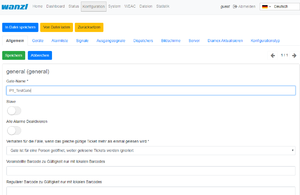
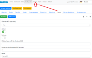
https://<IP-Adresse des Dashboards>Prüfen Sie hierzu auf dem Reiter Allgemein das der korrekte Gate-Name eingetragen ist.
Prüfen Sie dann auf dem Reiter Server folgende Punkte.
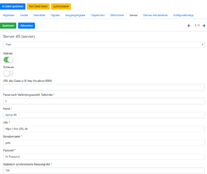
Server#0 (server)- muss auf Fern eingestellt sein.
Schiebeschalter Aktiviert ist aktiviert.
Unter Name* sollte ihr Server eingetragen sein.
Unter URL* sollte ihre URL eingetragen sein.
Unter Benutzername* sollte gate eingetragen sein.
Unter Passwort* sollte ihr Passwort eingetragen sein.
Am Ende Speichern.
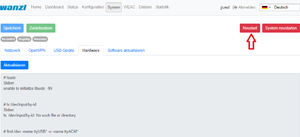
Im nächsten Schritt bitte in der oberen Leiste auf System klicken.
Sie bekommen jetzt folgende Darstellung, hier bitte einmal auf Neustart drücken.
Jetzt sollte Ihr neues Gate verbunden sein.
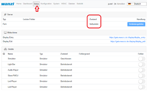
Sie können abschließend im Reiter Status noch die Verbindung prüfen. Unter Zustand muss jetzt VERBUNDEN erscheinen.
Edit existing Gate
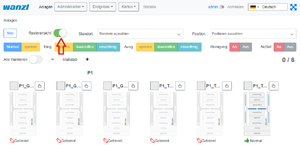
https://<dns-name or ip-address>/gatesSie befinden sich in der gleichen Ansicht wo Sie auch ein neues Gate anlegen würden.
Verschieben Sie hier bitte den Schiebeschalter "Rasteransicht" nach links.
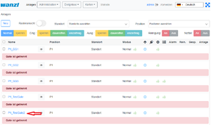
In der Ansicht klicken Sie auf den Namen des Gates welches Sie bearbeiten möchten (im Beispiel P1_TestGate2).
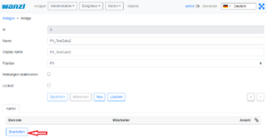
In dieser Ansicht bitte die Funktion "Bearbeiten" drücken.
In dieser Ansicht können Sie nun das Gate bearbeiten.
Remove Gate
https://<dns-name or ip-address>/gatesSie befinden sich in der gleichen Ansicht wo Sie auch ein neues Gate anlegen würden.
Verschieben Sie hier bitte den Schiebeschalter "Rasteransicht" nach links.
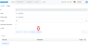
In der Ansicht klicken Sie auf den Namen des Gates welches Sie löschen möchten (im Beispiel P1_TestGate6).
In dieser Ansicht bitte die Funktion "Löschen" drücken.
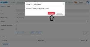
Es wird nun zur Sicherheit nochmal abgefragt ob Sie das Element wirklich löschen möchten? Bestätigen Sie dies bitte.
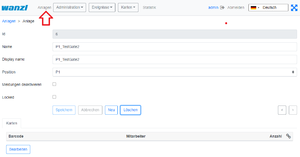
Sie bekommen nach dem Löschen schon automatisch das nächste Gate angezeigt (hier im Beispiel P1_TestGate2). Hier bitte auf Anlagen drücken.
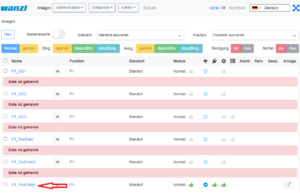
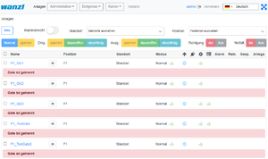
Sie sehen dann in der Rasteransicht das, das Gate P1_TestGate6 fehlt und erfolgreich gelöscht wurde.
Connectivity Board
| Contact | Type | Impulse | Description |
|---|---|---|---|
| A8 | Output | Yes (500 ms) | Person has entered |
| A9 | Output | Yes (500 ms) | Alarms* |
| E3 | Input | Yes (500 ms) | Open Entry |
| E4 | Input | Yes (500 ms) | Open Exit |
| E6 | Input | Yes (200ms) | Card is valid, open the gate |
| E7 | Input | Yes (200ms) | Card is invalid, do not open the gate |
| E8 | Input | No | Emergency State button** |
| E9 | Input | Yes (500 ms) | Open Entry 70% |
| E10 | Input | No | Fire Alarm |
*A9 Alarms:
- Gate is out of order, when a mandatory device is broken or a connection to the server is broken (if the server is used in the solution).
- Tailgating or other unwanted actions.
- Entry barcode scanner is broken or it is a stub.
- Gate in in the Fire Alarm or Emergency state. The alarm is produces as a repetitive pulse signal (700ms).
- Gate is open only for exit.
After the Emergency State button pressed, the gate switches to the Emergency State. Then only exit from this state is to restart the gate.
The signal can be set/received to/from a contact from any of the halves of the gate.
Configuration Management
User Interface
The Galaxy Gate is configured through the /configuration page. If the server is running at 192.168.1.221 and port is 8888, the url is:
http://192.168.1.221/configuration
There are two buttons on the page:
| Name | Description | Action |
|---|---|---|
| Save | Saves the modified configuration to the server | Post |
| Reset | Discards any changes by reloading the configuration from the server | Get |
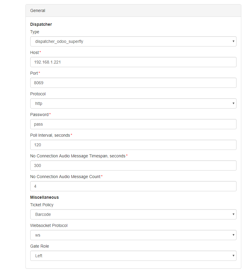
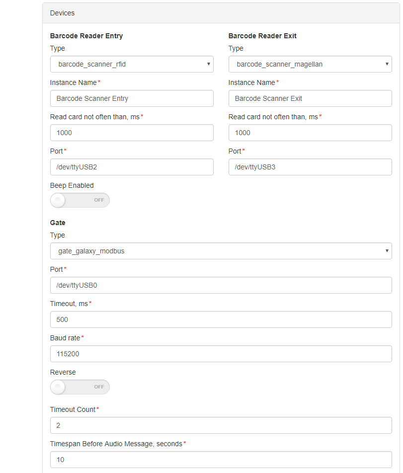
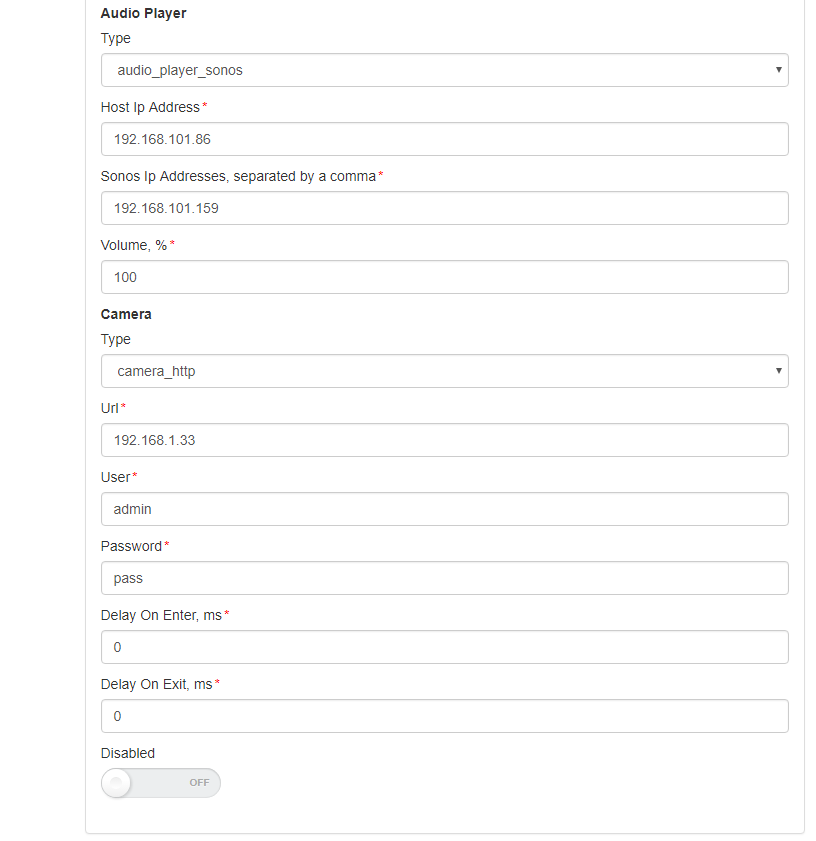
The configuration is split into sections and subsections:
- General
- Dispatcher
- Miscellaneous
- Devices
- Barcode Reader Entry
- Barcode Reader Exit
- Gate
- Tracking Camera
- Audio Player
- Camera
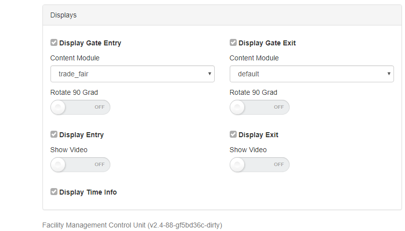
- Displays
- Display Gate Entry
- Display Gate Exit
- Display Entry
- Display Exit
- Display TimeInfo
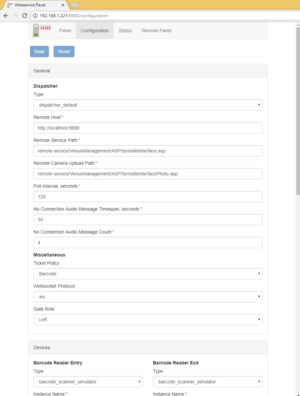
Here are some screenshots:
A subsection is often has a structure with a combo box named Type at the top and some fields that follow. This structure is used for configuring an entity that can have several implementations. What is important is that the implementation can differ in type and number of controls. For example, a simulator of the gate has only two properties:
Architecture
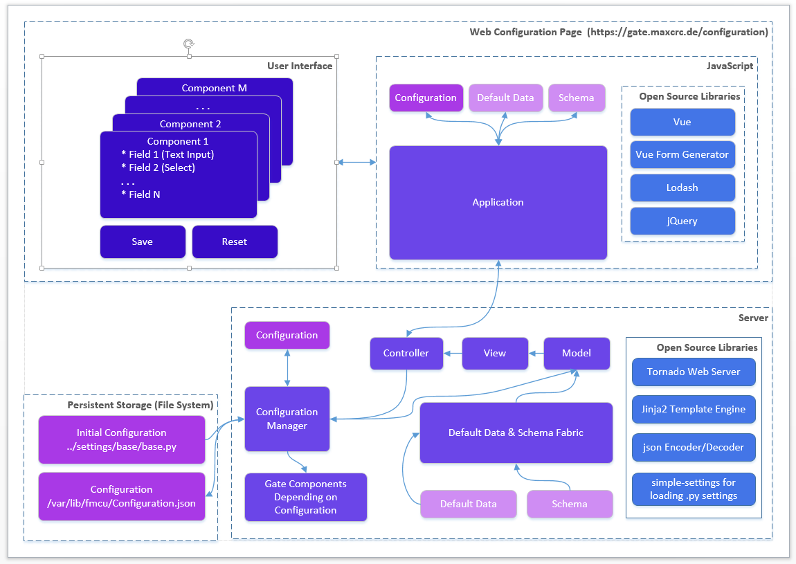
The picture below gives a bird's eye view of the configuration management.
When the gate starts and the Configuration.json is present it is created from the Initial Configuration (base.py or other .py configuration file). The Schema contains a set of data for describing controls in form components:
- Which controls should contain a component
- Validations rules if any
E.g. a form component can contain a text box and an input for integers. The data range for integer should 1-100.
The Default Data contains the initial data for controls in form components.
Edit this section
Roadmap
The features are planned for the upcoming release:
- Configurations page allows you to see the list of available configurations. You can:
- Clone an existing configuration to a new one
- Delete a configuration
- Make a configuration active. Only one configuration can be used by the server and it is called active.
- Apply button. This should apply changes on-the-fly.
- Restart button. This should restart the docker container and apply settings, which cannot be applied on-the-fly.
- Extend the vue form generator library:
- Make the switch control consistent with the switch controls on other pages
- Add a control which allows you to manage an array of items (e.g. the list of connected gates). E.g. https://codepen.io/safx/pen/AhCtk
- Import/Export of a Configuration.json.
- Reset any configuration to the default one (by removing the json file
Management of Events
The following sections contains the term Path, which means the path is part of the URL. E.g., path /events for the FMCU Server running under https://server.maxcrc.de/ means
https://server.maxcrc.de/events
Events
Web path:
/events
The page shows a filterable and sortable list of events:
| Name | Description |
|---|---|
| Date | Date and time when the event occurred |
| Name | Translated name of the event |
| Gate | Gate if appropriate where the event occurred |
| State | The state of the event if supported |
| Category | Category to which the event belongs to |
| Info | Additional info about the event |
Edit this section
Event Definitions Page
Path:
/event-definitions
The page shows a list of definitions of events:
| Name | Description |
|---|---|
| Name | Name |
| Event Definition Groups | Groups to which the event belongs to if any |
| Supported States | Can be empty (for impulse events) or On, Off (for the events with states) |
| Category | Category to which the event belongs to |
Edit this section
Event Definition Groups
Path:
/event-definition-groups
The page shows a list of event groups:
| Name | Description |
|---|---|
| Name | Name |
| Events | Event definitions assigned to the group |
| Delete | Delete button |
An event definition group allows you to group one or more events so that it can be bound to a user group. See Event Subscriptions below
Edit this section
Event Subscriptions
Web path:
/event-subscriptions
The page shows a list of event definition groups bound to a user groups.
| Name | Description |
|---|---|
| Group | User group |
| Event definition group | Event definition group |
| Locked | When locked, events are not sent to the users of the group |
| Info | Any informative text |
| Delete | Delete button |
When a event definition group is bound to a user group and not locked, new events from the event definition group are sent to the users from the user group. The user must have a valid email address.
Example. A user group Alarm events with two members user1 and user2 is bound to an event definition group Alarm events with two events GateTailgating and GateStateFireAlarm. When either or both of these events occur, both users user1 and user2 receive an email notification about that.
Edit this section
Configuration
Path:
/configuration
In order the emails with events can be sent out, the Email section with the information like the hostname, port etc. of the outgoing server and credentials should be properly configured.
