Gate ~ FMCU ~ Inbetriebnahme/en: Unterschied zwischen den Versionen
(Markierung: 2017-Quelltext-Bearbeitung) |
Inhaltsverzeichnis
- 1 Vorbereitung Preparation
-
2Technische Technical Information
- 2.1 Konfiguration Configuration
- 2.2 Prüfung Lichtleiste Test Lightbar
- 2.3 Prüfung Lichtband Test Lightband
- 3 Funktionstests Functional Tests
- 4 Einrichten der Anlage beim Kunden 5 Softwarebausteine
- Setting up the System at the Customer
-
5 Software Building Blocks
- 5.1 Standard I (horizontale Lichtleistehorizontal lightbar)
- 5.2 Standard II (vertikale Lichtleiste und horizontale Lichtleistevertical light bar and horizontal light bar)
- 5.3 Premium (horizontale und vertikale Lichtleiste horizontal and vertical light bar inkl. 1 DeckensensorCeiling Sensor)
- 5.4Erweitertes Tailgating durch Deckensensor (kein Einfluss auf Benutzeroberfläche Extended Tailgating by ceiling Sensor (no influence on user interface)
- 5.5 Zusatzoptionen Additional Options
- 5.6 Audiodateien Audio-Files
- 6 Verwandte Themen
VorbereitungPreparation[Bearbeiten | Quelltext bearbeiten]
Die Inbetriebnahme des Galaxy Gate wird durch Bereitstellung eines Image gestartet. Die Netzwerkkonfiguration wird mit einer statischen IP-Adresse vorbereitet. Die externe Kamera XOVIS ist außerdem mit einer statischen IP-Adresse ausgestattetThe commissioning of the Galaxy Gate is started by providing an image. The network configuration is prepared with a static IP address. The external camera XOVIS is also equipped with a static IP address.
| Device | IP address |
| Odroid IP | 192.168.1.100 |
| Xovis IP | 192.168.1.168 |
Diese initialen Parameter sind Bestandteil des Image. Alle weiteren Schritte basieren auf diese Konfiguration der IP-AdressenThese initial parameters are part of the image. All further steps are based on this configuration of the IP addresses.
The image is provided in the form of a file from maxcrc via a specified download URL. maxcrc updates the image in case of software changes such as bug fixes or the support of new hardware components. It must always be checked in advance whether the current image exists in the download area. Current sources are listed below.
| Image | Link |
| FMCU | 1.7.4 |
| WEAC | 30.21 |
| Diamex | 1.3.0 |
| WENI | 0.0.1 |
Mit dem Tool „Win32DiskImager“ wird nun das Image auf die SD-Karte übertragen. Das Tool kann hier heruntergeladen werden:
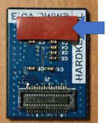 Richten Sie das eMMC Modul und den eMMC-Anschluss auf der ODROID-C2-Platine bündig aus, wobei das weiße Rechteck auf der Platine als Richtlinie dient.
Drücken Sie die eMMC langsam ein, bis die Karte hörbar einrastet.
Jetzt wird der Einplatinencomputer mit einem Computer über ein Netzwerkkabel verbunden. Nach dem Einschalten der Spannungsversorgung der Zutrittskontrolle kann mit einem Internet-Browser (z.B. Chrome) die Konfiguration fortsetzen.USB-Anschlussbelegung ODROID

In der nachfolgenden Darstellung ist die Anschlussbelegung des Einplatinencomputers aufgeführt.
This file is now extracted and copied to the eMMC card using a software tool. This process can be performed on any Windows computer that has a card reader with a micro SD slot.
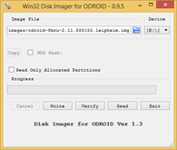
The image is now transferred to the SD card using the "Win32DiskImager" tool. The tool can be downloaded here:
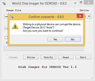
After launching the program, select the previously extracted image file. The device letter is the drive assigned to the SD card on the PC. Make sure the eMMC adapter and eMMC card are properly inserted before clicking the button. You must confirm the writing before the process begins. After writing, you need to click on the "Verify" button to ensure that the written data has been transferred to the eMMC card without errors.
The final step is to insert the prepared eMMC card into the ODROID single-board computer.
Remove the protective film of the double-sided tape:
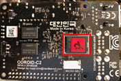
Align the eMMC module and the eMMC connector flush on the ODROID-C2 board using the white rectangle on the board as a guide.
Slowly push in the eMMC until the card clicks into place.
Now the single-board computer is connected to a computer via a network cable. After switching on the power supply of the access control, the configuration can be continued with an Internet browser (e.g. Chrome).
USB-Pinout ODROID
The pin assignment of the single-board computer is shown in the following illustration.
| Connection | Description |
|---|---|
| USB1 | |
| USB2 | RS232-Adapter für for DUOmetrics |
| USB3 | LED-Controller für for LED-Matrix und and LED-Lichtband Lightband |
| USB4 | USB-RS485 nano Adapter für for WEAC-Board |
Technische Technical Information[Bearbeiten | Quelltext bearbeiten]
KonfigurationConfiguration[Bearbeiten | Quelltext bearbeiten]
In der URL-Leiste des Browsers wird die IP-Adresse The IP address is entered in the browser's URL bar. http://192.168.1.100 eingegeben. Es erscheint folgendes Anmeldefenster
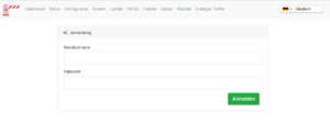 Folgende Anmeldeinformationen sind hinterlegt:
The following login window appears
The following login information is stored:
| Username | Password |
|---|---|
| wanzl | wanzlfmcu! |
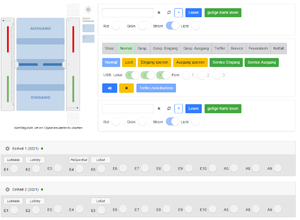
Nach erfolgreicher Anmeldung erscheint diese AnsichtAfter successful login, this view appears.
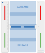
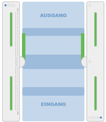
In dieser Darstellung kann man bereits unterschiedliche Informationen ablesen und Zustände der Zutrittskontrolle ermitteln. Die linke visuelle Darstellung der Zutrittskontrolle beschreibt den aktuellen Zustand. Wenn die Bügelbeleuchtung nicht rot blinkt ist der Zustand normal und die Verbindung zwischen FMCU und WEAC wurde erfolgreich aufgebaut. Die beiden LED-Anzeigen der horizontalen Darstellung von Einheit 1 bzw. Einheit 2 signalisieren ebenfalls visuell den Verbindungszustand. In Klammern wird die aktuelle Version der WEAC-Firmware angezeigt.
Im Fehlerfall muss man die Adresse des USB-Zugangs prüfen. Auf der Systemseite der Anwendung this representation you can already read different information and determine the status of the access control. The left visual representation of the access control describes the current status. If the bracket light is not flashing red, the condition is normal and the connection between FMCU and WEAC has been established successfully. The two LED displays in the horizontal display of unit 1 and unit 2 also indicate the connection status visually. The current version of the WEAC firmware is shown in brackets.
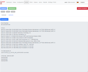
In the event of an error, you must check the address of the USB access. On the system page of the application (http://192.168.1.100/system) werden alle verwendeten USB-Anschlüsse angezeigtall USB ports used are displayed.
In diesem Beispiel sind drei Komponenten angeschlossenthis example, three components are connected.
| Anschluss Connection | Vewendungszweck Usage |
|---|---|
| /dev/ttyUSB2 | Komponente1 Components1 |
| /dev/ttyUSB1 | Komponente2 Components2 |
| /dev/ttyUSB0 | Komponente3 |
| Components3 |
The connection to WEAC is always shown with the USB0 or USB1 connections. You can check the current settings by looking at the configuration of the gate (http://192.168.1.100/configuration#gate)
Die Einstellung der Adresse des USB-Anschlusses zum WEAC Board befindet sich weiter unten auf diesem Dialog. Bei der Slave FMCU wird bei Gate "Simulator" eingestellt.
Bei Verwendung einer Slave FMCU wird über die Menüführung Setting the address of the USB port to the WEAC board is further down this dialog. "Simulator" is set for Gate on the Slave FMCU.
When using a slave FMCU, the IP address is set via the menu (http://192.168.1.100/configuration#slave_fmcu) die IP-Adresse eingestellt.
Weiterhin muss in der Whiteliste unter "Authentication und verlinkte Gates" die IP-Adresse eingetragen werden Furthermore, the IP address must be entered in the white list under "Authentication and linked gates".
Master-FMCU: 192.168.1.101, Slave-FMCU: 192.168.1.100 Bei Verwendung der Lichtleiste ist ebenfalls darauf zu achten, dass alle drei Sensoren aktiviert sind.

Die Parameter der Lichtleiste werden über die Menüführung When using the light bar, it is also important to ensure that all three sensors are activated.
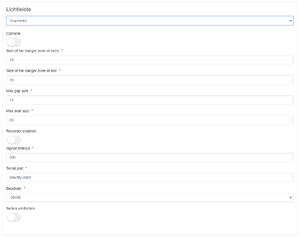
The parameters of the light bar are set via the menu navigation (http://192.168.1.100/configuration#light_bar) durchgeführt.
Die hier aufgeführten Werte können als Standard übernommen werden. Bevor die Lichtleiste verwendet werden kann, muss ein Selbstabgleich durchgeführt werden. Nachfolgende werden diese Schritte erläutert.
1. Es liegt keine Versorgungsspannung am Lichtleisencontroller an. Das Gerät ist ausgeschaltet. 2. Überwachungsbereich ist freiThe values listed here can be accepted as standard. Before the light bar can be used, a self-adjustment must be carried out. These steps are explained below.
1. There is no supply voltage at the light bar controller. The device is switched off.
2. Monitoring area is free.
3. DIP3 auf to ON (Auswertung auf Evaluation on LVX Platineboard)
4. Gerät einschaltenturn on a device.
5. LEDs kontrollieren check:
Die grüne The green LED D soll leuchtenshould light up. (Auswertung auf evaluation on LVX Platineboard)
Kein Blinken oder Leuchten der roten Fehler-No blinking or glowing of the red error LEDs.
6. DIP3 im Betrieb wieder auf OFFback to OFF during operation.
=> Das Gerät speichert die Werte im EEPROM und geht in den Normalbetrieb. Falls Sie die Einstellung nicht speichern wollen: Versorgung abschalten, solange der DIP3 auf ON ist. Hinweis:
Wird das Gerät während des Speicherns der Bezugswerte ausgeschaltet (bevor LED “B“ blinkt), kann dies zu unbeabsichtigten Ausblendungen führen.
LED Zustände beim Selbstabgleich The device saves the values in the EEPROM and goes into normal operation. If you do not want to save the setting: Switch off the supply as long as DIP3 is ON.
Notice:
If the device is switched off while the reference values are being saved (before LED "B" flashes), this can lead to unintentional blanking.
LED states during self-adjustment
Nachdem alle Einstellungen geprüft und gegebenenfalls angepasst worden sind, kann man auf der Dashboardseite unterschiedliche Aktionen durchführen.
| On or blink |
Self-alignment failed!
Individual beams are recognized as defective. Only emergency operation is possible! |
||||
After all settings have been checked and adjusted if necessary, you can carry out various actions on the dashboard page.
Depending on the action, the following states are displayed graphically in the view (http://192.168.1.100/dashboard) dargestellt.
.
Test Lightbar[Bearbeiten | Quelltext bearbeiten]
Die Lichtleiste des Herstellers Duometrics muss zunächst mit dem richtigen Modus kalibriert werden. Die Details können der Anleitung der Hardware entnommen werden. Nach Abschluss der Kalibrierung muss das Anschlussboard diese Einstellungen aufweisen.
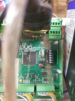
Die korrekte Konfiguration der Lichtleiste kann auf der Statusseite The light bar from the manufacturer Duometrics must first be calibrated with the correct mode. The details can be found in the hardware instructions. After the calibration is complete, the connector board must have these settings.
The correct configuration of the light bar can be checked on the status page (http://192.168.1.100/status) der Anwendung geprüft werdenof the application.
Wenn ein Fehler in der Kommunikation auftritt, wird dieser Fehler hier entsprechend angezeigtIf an error occurs in the communication, this error is displayed here accordingly.
Nachdem die Einstellungen geprüft worden sind, kann man die Funktion testen, indem in Eingangsrichtung der Zustand "Dauerfrei" eingestellt wird. Dies geschieht über die Konfiguration des Barcodelesegerätes After the settings have been checked, the function can be tested by setting the "Permanently free" status in the entry direction. This is done via the configuration of the barcode reader (http://192.168.1.100/configuration#barcode_scanner_entry). Dort wird der Eintrag There the entry "Light Bar" ausgewähltis selected.
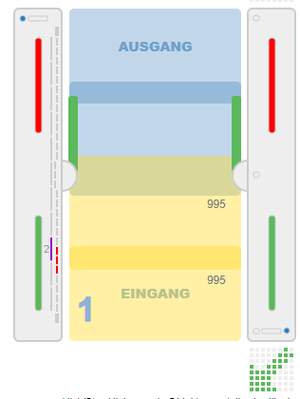
Danach kann eine Person in Eingangsrichtung das Gate durchschreiten. Auf dem Dashboard wird diese Aktion visuell dargestellt.
 Damit ist die Prüfung der Lichtleiste abgeschlossen. Prüfung Lichtband
After that, one person can walk through the gate in the direction of entry. This action is represented visually on the dashboard.
This completes the check of the light bar.
Test Lightband[Bearbeiten | Quelltext bearbeiten]
Das Lichtband wird mit der Komponente Diamex gesteuert. Den Status der Erreichbarkeit dieser Komponente kann man auf der Seite The light band is controlled with the Diamex component. The availability status of this component can be displayed on the page. (http://192.168.1.100/update) dargestellt.
Dieser Status wird nur nach Konfiguration des Lichtbandes für Master und Slave korrekt dargestellt.
Man muss die aktuellen Motive für die Lichtsteuerung auf das Modul laden. Die Datei befindet sich hier:
Der Status der Komponente kann wie bei allen anderen Komponenten auf der Statusseite This status is only displayed correctly after configuration of the light band for master and slave.
You have to load the current motifs for the light control onto the module. The file is located here:
As with all other components, the status of the component can be checked on the status page. (http://192.168.1.100/status) geprüft werden.
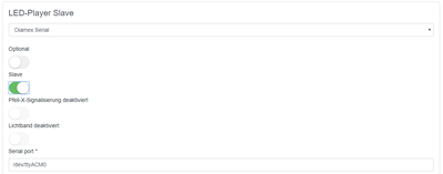
Es gilt zu beachten das es zwei Komponenten für die Lichtbandsteuerung gibt. Für jeden Rahmen sind unterschiedliche Konfigurationsparameter zu berücksichtigen. Es werden grundsätzlich Master und Slave definiert.
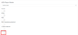
Wenn keine LED-Matrix vorhanden ist, sollte "No matrix" It should be noted that there are two components for the light line control. Each frame has different configuration parameters to consider. Master and slave are always defined.
If there is no LED matrix, "No matrix" should be activated.(https://192.168.1.100/configuration#led_player_master) aktiviert werden.
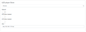
Das Lichtband muss auf beiden Rahmenhälften ein synchrones Verhalten aufweisen. Darum wird auf der Masterseite die Kommunikation mit der Slaveseite eingestellt.
Darstellung The light band must behave synchronously on both halves of the frame. For this reason, communication with the slave side is set on the master side.
Display Master FMCU (http://192.168.1.101/api)
FunktionstestsFunctional Tests[Bearbeiten | Quelltext bearbeiten]Einrichten der Anlage beim Kunden
Setting up the System at the Customer[Bearbeiten | Quelltext bearbeiten]
Beim Aufbau der Anlage im Kundennetzwerk muss zunächst die Netzwerkkonfiguration angepasst werden. Dazu meldet man sich mit wie bereits bei der Inbetriebnahme über den Web-Browser mit den hinterlegten Anmeldeinformationen an, nachdem der Computer über das Netzwerk mit der Zutrittskontrolle verbunden worden ist.
Jetzt wechselt man auf die Seite System When setting up the system in the customer network, the network configuration must first be adjusted. To do this, you log in with the web browser with the stored login information, as you did during commissioning, after the computer has been connected to the access control system via the network.
Now go to the System page and select the Network tab there. (http://192.168.1.100/system) und wählt dort den Reiter Netzwerk aus.
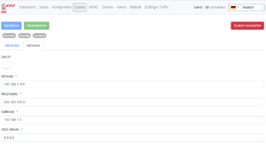
Hier trägt man die vom Kunden bereitgestellten Netzwerk-Informationen für IP-Adresse, Netzmaske, Gateway und DNS-Server ein, klickt auf Speichern und startet das System (System neu starten) neu. Danach wird das Netzwerkkabel des Kundennetzwerkes mit der Anlage verbunden und die weiteren Einstellungen können mit jedem PC im Kundennetzwerk fortgesetzt werden.
Softwarebausteine
Here you enter the network information provided by the customer for IP address, net mask, gateway and DNS server, click on Save and restart the system (Restart system). Then the network cable of the customer network is connected to the system and the other settings can be continued with any PC in the customer network.
Software Building Blocks[Bearbeiten | Quelltext bearbeiten]
Die Benutzeroberfläche unterstützt die Konfiguration der Zutrittskontrolle durch standardisierte Abläufe, die in Form so genannter Softwarebausteine zusammengefasst werden. Die einzelnen Einstellungsmöglichkeiten werden nachfolgend aufgeführt. Die verschiedenen Einstellungen werden in Kategorien gebündelt und orientieren sich an ähnlichen BewegungsabläufenThe user interface supports the configuration of the access control through standardized processes that are summarized in the form of so-called software modules. The individual setting options are listed below. The various settings are bundled into categories and are based on similar movement sequences.
Standard I (horizontale Lichtleistehorizontal lightbar)[Bearbeiten | Quelltext bearbeiten]
| Funktion Function | Beschreibung Description | Standard |
|---|---|---|
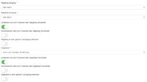
| Tailgating Eingang Die Zutrittskontrolle ist für den Einzeldurchgang konfiguriert. Die Prüfung des Durchgangs erfolgt durch Präsentieren des Tickets am Kartenleser. Wenn nach dem Durchgang einer erfolgreichen Prüfung eine zweite Person ohne Prüfung den Durchgang nutzt, wird ein Alarm mit visuellem und akustischem Alarm ausgelöst. Die Zutrittskontrolle kann entweder wie folgt reagieren. Es wird sofort der Schließvorgang gestartet ohne Berücksichtigung von Personen im Schwenkbereich. Der Schließvorgang startet nur dann, wenn sich keine Person im Schwenkbereich befindet.
Folgende Optionen ergeben sich daraus: - kein Entry |
Access control is configured for single pass. The passage is checked by presenting the ticket at the card reader. If, after passing a successful test, a second person uses the passage without a test, an alarm with visual and audible alarm is triggered. The access control can either react as follows. The closing process is started immediately, regardless of people in the pivoting area. The closing process only starts when nobody is in the pivoting area.
This results in the following options: - no Alarm - Alarm - Alarm und Schließen nach Verlassen des Schwenkbereich and closing after leaving the swivel range - Alarm und sofort Schließen keinand close immediately |
no Alarm |
| Tailgating Ausgang | Die Beschreibung ist analog der Funktion "Tailgating Eingang" | kein Alarm |
| Lichtleiste wird zum Erkennen des Tailgating verwendet | Wenn dieser Schalter aktiviert ist, wird die Lichtleiste für die Personenerkennung verwendet. | aktiviert |
| Deckensensor wird zum Erkennen des Tailgating verwendet | Wenn dieser Schalter aktiviert ist, wird der Deckensensor für die Personenerkennung verwendet. | nicht aktiviert |
| Tailgating in dem ganzen Durchgang erkennen | Diese Funktion kann nur bei Verwendung des Deckensensors genutzt werden. Die Fläche vor dem Glasbügel ist in zwei Zonen eingeteilt. Es gibt eine "Outerzone" und eine "Innerzone". Wenn diese Funktion aktiviert ist, wird die 2. Person bereits in der "Outerzone" erkannt. Der Alarm kann also zu einem früheren Zeitpunkt erfolgen. | nicht aktiviert |
| Gegenlauf |
Bei Verwendung der Lichtleiste erfolgt die Identifizierung mit dem Eintritt in den Rahmen. Bei Verwendung der Kamera kann dieser Effekt bereits vor Eintritt des Rahmens entdeckt werden. Es sind folgende Optionen möglich:
- kein Alarm - Alarm - Alarm und Schließen nach Verlassen des Schwenkbereich - Alarm und sofort Schließen |
kein Alarm |
| Lichtleiste wird zum Erkennen des Gegenlauf verwendet | Wenn dieser Schalter aktiviert ist, wird die Lichtleiste als Sensor verwendet. | aktiviert |
| Deckensensor wird zum Erkennen des Gegenlauf verwendet | Wenn dieser Schalter aktiviert ist, wird der Deckensensor als Sensor verwendet. | nicht aktiviert |
| Gegenlauf in dem ganzen Durchgang erkennen | Diese Funktion kann nur bei Verwendung des Deckensensors genutzt werden. Die Fläche vor dem Glasbügel ist in zwei Zonen eingeteilt. Es gibt eine "Outerzone" und eine "Innerzone". Wenn diese Funktion aktiviert ist, wird die 2. Person bereits in der "Outerzone" erkannt. Der Alarm kann also zu einem früheren Zeitpunkt erfolgen. | nicht aktiviert |
| Exit | The description is analogous to the "Tailgating input" function | no Alarm |
| Light bar is used to detect Tailgating | If this switch is activated, the light bar is used for person detection. | activated |
| Ceiling sensor is used to detect tailgating | If this switch is activated, the ceiling sensor is used for people detection. | not activated |
| Detect tailgating throughout the run | This function can only be used when using the ceiling sensor. The area in front of the glass bracket is divided into two zones. There is an "outer zone" and an "inner zone". If this function is activated, the 2nd person is already recognized in the "outer zone". The alarm can therefore be given at an earlier point in time. | not activated |
| reverse |
When using the light bar, identification occurs when entering the frame. When using the camera, this effect can be detected before the frame enters. The following options are possible:
- no Alarm - Alarm - Alarm and closing after leaving the swivel range - Alarm and close immediately |
no Alarm |
| Light bar is used to detect reverse rotation | When this switch is activated, the light bar is used as a sensor. | activated |
| Ceiling sensor is used to detect counter-rotation | If this switch is activated, the ceiling sensor is used as a sensor. | not activated |
| Detect reverse flow throughout the passage | This function can only be used when using the ceiling sensor. The area in front of the glass bracket is divided into two zones. There is an "outer zone" and an "inner zone". If this function is activated, the 2nd person is already recognized in the "outer zone". The alarm can therefore be given at an earlier point in time. | not activated |
Standard II (vertical light bar and horizontal light bar)[Bearbeiten | Quelltext bearbeiten]
| Funktion Function | Beschreibung Description | Standard |
|---|---|---|
| Höhendefinition bei eintretenden Objekten (insbesondere KinderHeight definition for entering objects (especially children) | ||
Premium (horizontale und vertikale Lichtleiste horizontal and vertical light bar inkl. 1 DeckensensorCeiling Sensor)[Bearbeiten | Quelltext bearbeiten]
| Funktion Function | Beschreibung Description | Standard | Höhendefinition bei eintretenden Objekten (insbesondere Kinder). Person darf mit Trolley das Gate passieren. Anschließend schließen die Schwenkarme nach verlassen des Schwenkbereichs | Erweitertes Tailgating durch Deckensensor (kein Einfluss auf Benutzeroberfläche) |
|---|
| Height definition for entering objects (especially children). person may pass through the gate with a trolley. The swivel arms then close after leaving the swivel range | ||
| Extended tailgating by ceiling sensor (no influence on user interface) | ||
Extended Tailgating by ceiling Sensor (no influence on user interface)[Bearbeiten | Quelltext bearbeiten]
| Funktion Function | Beschreibung Description | Standard | Einzelerkennung am Kartenleser, die Lesebereiche dürfen immer nur Einzel betreten werden, ansonsten öffnet das Gate nicht. Bei Manipulationsversuch schließt das Gate in jedem Fall. | zus. Überwachung von Flächen im Umfeld der Zutrittskontrolle |
|---|
| Individual recognition on the card reader, the reading areas may only be entered individually, otherwise the gate will not open. In the event of an attempt at manipulation, the gate closes in any case. | ||
| additional monitoring of areas in the vicinity of the access control | ||
Additional Options[Bearbeiten | Quelltext bearbeiten]
| Funktion Function | Beschreibung Description | Standard |
|---|---|---|
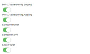
| PfeilArrow-X-Signalisierung Eingang Signal Entry Pfeil | ||
| Arrow-X -Signalisierung Ausgang Lichtband Signal Exit | ||
| Lightband Master | ||
| Lichtband Lightband Slave | ||
| Lautsprecher Speaker |
AudiodateienAudio-Files[Bearbeiten | Quelltext bearbeiten]
Die Zuordnung der MP3-Datei-Namen zur Verwendung kann der folgenden Tabelle entnommen werdenThe assignment of the MP3 file names for use can be found in the following table:
| Name Funktion | Function |
|---|---|
| MP3_1.mp3 | Beep nachdem ein Barcode gelesen worden ist after a Barcode has been read |
| MP3_2.mp3 | Bitte gehen Sie durch das Please go through the Gate |
| MP3_3.mp3 | Zufälliger Treffer Random Hit |
| MP3_4.mp3 | Alarm |
| MP3_5.mp3 Den Leserbereich bitte einzeln betreten | Please enter the readers' area individually |
| MP3_6.mp3 Bitte | verlassen Sie den Leserbereich Please leave the readers area |
| MP3_7.mp3 | Notauf Emergency |
Verwandte Themen
- Galaxy Gate Bedienungsanleitung Beschreibung zentrales Operation Manual
- Description Central Dashboard
{{translate|Gate ~ Installation}}
{{DISPLAYTITLE:Gate ~ Installation}}
__TOC__
<br />
<br />
<br />
<br />
==Vorbereitung==
Die Inbetriebnahme des Galaxy Gate wird durch Bereitstellung eines Image gestartet. Die Netzwerkkonfiguration wird mit einer statischen IP-Adresse vorbereitet. Die externe Kamera XOVIS ist außerdem mit einer statischen IP-Adresse ausgestattetPreparation==
The commissioning of the Galaxy Gate is started by providing an image. The network configuration is prepared with a static IP address. The external camera XOVIS is also equipped with a static IP address.
{| class="wikitable"
|'''Device'''
|'''IP address'''
|-
|Odroid IP
|192.168.1.100
|-
|Xovis IP
|192.168.1.168
|}
Diese initialen Parameter sind Bestandteil des Image. Alle weiteren Schritte basieren auf diese Konfiguration der IP-Adressen.
{{Box_Hinweis|Hinweis Text = Die Netzwerkkonfigurationsparameter müssen überprüft werden, bevor die Hardware an den Kunden geliefert wird, um sicherzustellen, dass die Zutrittskontrolle ordnungsgemäß funktioniert. Darüber hinaus hängen die RFID-Leserkomponenten von den Kundenanforderungen ab. Die korrekte Konfiguration der These initial parameters are part of the image. All further steps are based on this configuration of the IP addresses.
{{Hint|text = The network configuration parameters must be verified before the hardware is shipped to the customer to ensure access control is working properly. In addition, the RFID reader components depend on customer requirements. The correct configuration of the '''F'''acility '''M'''anagement '''C'''ontrol '''U'''nit (FMCU) ist für die erfolgreiche Implementierung beim Kunden unerlässlich.}}Das Image wird in Form einer Datei von maxcrc über eine angegebene Download-URL bereitgestellt. maxcrc aktualisiert das Image im Falle von Softwareänderungen wie Fehlerbehebungen oder der Unterstützung neuer Hardwarekomponenten. Im Vorfeld muss immer geprüft werden, ob das aktuelle Image im Downloadbereich existiert. Nachfolgend sind die aktuellen Quellen aufgeführtis essential for a successful implementation at the customer.}}The image is provided in the form of a file from maxcrc via a specified download URL. maxcrc updates the image in case of software changes such as bug fixes or the support of new hardware components. It must always be checked in advance whether the current image exists in the download area. Current sources are listed below.
{| class="wikitable"
|'''Image'''
|'''Link'''
|-
|FMCU
|[http://nas0.dnsalias.com:5000/sharing/ElLnAs011 1.7.4]
|-
|WEAC
|[http://nas0.dnsalias.com:5000/sharing/JmBYWVtYt 30.21]
|-
|Diamex
|[http://nas0.dnsalias.com:5000/sharing/7O8ApOKoq 1.3.0]
|-
|WENI
|[http://nas0.dnsalias.com:5000/sharing/OXfYsL9YP 0.0.1]
|}
Diese Datei wird nun extrahiert und mit einem Software-Tool auf die eMMC-Karte kopiert. Dieser Vorgang kann mit jedem Windows-Computer ausgeführt werden, auf dem ein Kartenleser mit einem Micro-SD-Steckplatz verfügbar ist.<br />Mit dem Tool „Win32DiskImager“ wird nun das Image auf die SD-Karte übertragen. Das Tool kann hier heruntergeladen werdenThis file is now extracted and copied to the eMMC card using a software tool. This process can be performed on any Windows computer that has a card reader with a micro SD slot.<br />The image is now transferred to the SD card using the "Win32DiskImager" tool. The tool can be downloaded here:
[https://dn.odroid.com/DiskImager_ODROID/ DiskImager_ODROID]
<br />
{{Mehrere Bilder
| Kopfzeile = Hilfsmittel zum Übertagen der Image-Datei auf die SD Karte
| align = center
| Hintergrund = #EDEDED
| Bild1 = MicroSD Cover.png
| Untertitel1 = MicroSD Cover
| Breite1 = 200
| Bild2Multiple Images
| Headline = Tools for transferring the image file to the SD card
| align = center
| Background = #EDEDED
| Image1 = MicroSD Cover.png
| Subtitle1 = MicroSD Cover
| Width1 = 200
| Image2 = image SD card cover.png
| Untertitel2Subtitle2 = SD card
| Breite2Width2 = 200
| Bild3Image3 = image SD card Leser.png
| Untertitel3Subtitle3 = SD Card Leser
| Breite3Width3 = 350
}}
<br />Nach dem Starten des Programms wählen Sie die zuvor extrahierte Bilddatei aus. Der Gerätebuchstabe ist das Laufwerk, das der SD-Karte auf dem PC zugewiesen ist. Stellen Sie sicher, dass der eMMC Adapter und die eMMC-Karte ordnungsgemäß eingesteckt sind, bevor Sie auf die Schaltfläche klicken. Sie müssen den Schreibvorgang bestätigen, bevor der Prozess beginnt. Nach dem Schreiben müssen Sie auf die Schaltfläche „Überprüfen“ klicken, um sicherzustellen, dass die geschriebenen Daten fehlerfrei auf die eMMC-Karte übertragen wurden. <br />{{Mehrere Bilder
| Kopfzeile = Benutzeroberfläche After launching the program, select the previously extracted image file. The device letter is the drive assigned to the SD card on the PC. Make sure the eMMC adapter and eMMC card are properly inserted before clicking the button. You must confirm the writing before the process begins. After writing, you need to click on the "Verify" button to ensure that the written data has been transferred to the eMMC card without errors. <br />{{Mehrere Bilder
| Headline = User Interface Image Tool
| align = center
| HintergrundBackground = #EDEDED
| BreiteWidth = 250
| Bild1Image1 = image tool dialog.png
| Untertitel1Subtitle1 = Imagetool Dialog
| Bild2Image2 = image tool confirmation dialog.png
| Untertitel2 = Bestätigung Schreibvorgang
| Bild3Subtitle2 = Write Confirmation
| Image3 = image ODROID SD card cover.png
| Untertitel3Subtitle3 = ODROID Ansicht Kartensteckplatz
}}
Der letzte Schritt besteht darin, die vorbereitete eMMC-Karte in den Einplatinencomputer ODROID einzulegen.
Entfernen Sie den Schutzfilm des doppelseitigen KlebebandesCard Slot View
}}
The final step is to insert the prepared eMMC card into the ODROID single-board computer.
Remove the protective film of the double-sided tape:
<br />
[[Datei:eMMC adhesive tape.png|alternativtext=eMMC-Karte|mini|ohne]]
Richten Sie das eMMC Modul und den eMMC-Anschluss auf der ODROID-C2-Platine bündig aus, wobei das weiße Rechteck auf der Platine als Richtlinie dient.
Drücken Sie die eMMC langsam ein, bis die Karte hörbar einrastet.
<br />Jetzt wird der Einplatinencomputer mit einem Computer über ein Netzwerkkabel verbunden. Nach dem Einschalten der Spannungsversorgung der Zutrittskontrolle kann mit einem Internet-Browser (z.B. Chrome) die Konfiguration fortsetzen.
'''USB-AnschlussbelegungAlign the eMMC module and the eMMC connector flush on the ODROID-C2 board using the white rectangle on the board as a guide.
Slowly push in the eMMC until the card clicks into place.
<br />Now the single-board computer is connected to a computer via a network cable. After switching on the power supply of the access control, the configuration can be continued with an Internet browser (e.g. Chrome).
'''USB-Pinout ODROID'''
[[Datei:USB-ODROID.png|ohne|mini]]
In der nachfolgenden Darstellung ist die Anschlussbelegung des Einplatinencomputers aufgeführt.
{| class="wikitable"
!'''Anschluss'''
!'''BeschreibungThe pin assignment of the single-board computer is shown in the following illustration.
{| class="wikitable"
!'''Connection'''
!'''Description'''
|-
|USB1
|
|-
|USB2
|RS232-Adapter fürfor DUOmetrics
|-
|USB3
|LED-Controller fürfor LED-Matrix undand LED-LichtbandLightband
|-
|USB4
|USB-RS485 nano Adapter fürfor WEAC-Board
|}
==TechnischeTechnical Information==
===Konfiguration===
In der URL-Leiste des Browsers wird die IP-Adresse Configuration===
The IP address is entered in the browser's URL bar. '''<nowiki>http://192.168.1.100</nowiki>'''
eingegeben. Es erscheint folgendes Anmeldefenster
The following login window appears
[[Datei:Anmeldung FMCU.png|ohne|mini]]
Folgende Anmeldeinformationen sind hinterlegt:
{| class="wikitable"
|+
!Benutzename
!Passwort
|-
|wanzl
|wanzlfmcu!
|}
Nach erfolgreicher Anmeldung erscheint diese AnsichtThe following login information is stored:
{| class="wikitable"
|+
!Username
!Password
|-
|wanzl
|wanzlfmcu!
|}
After successful login, this view appears.
[[Datei:Dashboard FMCU de.png|ohne|mini]]
In dieser Darstellung kann man bereits unterschiedliche Informationen ablesen und Zustände der Zutrittskontrolle ermitteln. Die linke visuelle Darstellung der Zutrittskontrolle beschreibt den aktuellen Zustand. Wenn die Bügelbeleuchtung nicht rot blinkt ist der Zustand normal und die Verbindung zwischen FMCU und WEAC wurde erfolgreich aufgebaut. Die beiden LED-Anzeigen der horizontalen Darstellung von Einheit 1 bzw. Einheit 2 signalisieren ebenfalls visuell den Verbindungszustand. In Klammern wird die aktuelle Version der WEAC-Firmware angezeigt.
{{Mehrere Bilder
| Kopfzeile = Status der Erreichbarkeit der WEAC Einheiten
| Richtungthis representation you can already read different information and determine the status of the access control. The left visual representation of the access control describes the current status. If the bracket light is not flashing red, the condition is normal and the connection between FMCU and WEAC has been established successfully. The two LED displays in the horizontal display of unit 1 and unit 2 also indicate the connection status visually. The current version of the WEAC firmware is shown in brackets.
{{Multiple Images
| Headline = #EDEDED
| Direction = vertical
| align = left
| center = 1
| Breite = 400
| Hintergrund = #EDEDED
| Bild1 Image1 = Gate Status ok.png
| Untertitel1Subtitle1 = WEAC Einheit verfügbar
| Bild2Unit available
| Image2 = Gate Status wrong.png
| Untertitel2Subtitle2 = WEAC Einheit nicht verfügbar
}}
Im Fehlerfall muss man die Adresse des USB-Zugangs prüfen. Auf der Systemseite der Anwendung Unit not available
}}
In the event of an error, you must check the address of the USB access. On the system page of the application ('''<nowiki>http://192.168.1.100/system</nowiki>''') werden alle verwendeten USB-Anschlüsse angezeigtall USB ports used are displayed.
[[Datei:image system page.png|ohne|mini]]
In diesem Beispiel sind drei Komponenten angeschlossen.
{| class="wikitable"
|+
!Anschluss
!Vewendungszweck
|-
|/dev/ttyUSB2
|Komponente1
|-
|/dev/ttyUSB1
|Komponente2
|-
|/dev/ttyUSB0
|Komponente3
|}
Die Verbindung zu WEAC wird immer mit den Anschlüssen USB0 bzw. USB1 abgebildet. Die aktuellen Einstellungen kann man prüfen, indem man sich die Konfiguration des Gate anschautthis example, three components are connected.
{| class="wikitable"
|+
!Connection
!Usage
|-
|/dev/ttyUSB2
|Components1
|-
|/dev/ttyUSB1
|Components2
|-
|/dev/ttyUSB0
|Components3
|}
The connection to WEAC is always shown with the USB0 or USB1 connections. You can check the current settings by looking at the configuration of the gate ('''<nowiki>http://192.168.1.100/configuration#gate</nowiki>''')
[[Datei:Gate Modbus.png|ohne|mini]]
Die Einstellung der Adresse des USB-Anschlusses zum WEAC Board befindet sich weiter unten auf diesem Dialog. Bei der Slave FMCU wird bei Gate "Simulator" eingestelltSetting the address of the USB port to the WEAC board is further down this dialog. "Simulator" is set for Gate on the Slave FMCU.
[[Datei:Gate Port.png|ohne|mini]]
Bei Verwendung einer Slave FMCU wird über die Menüführung When using a slave FMCU, the IP address is set via the menu ('''<nowiki>http://192.168.1.100/configuration#slave_fmcu</nowiki>''') die IP-Adresse eingestellt.
[[Datei:slave fmcu.png|ohne|mini]]
Weiterhin muss in der Whiteliste unter "Authentication und verlinkte Gates" die IP-Adresse eingetragen werdenFurthermore, the IP address must be entered in the white list under "Authentication and linked gates".
[[Datei:whitelist.png|ohne|mini]]
Master-FMCU: 192.168.1.101, Slave-FMCU: 192.168.1.100
Bei Verwendung der Lichtleiste ist ebenfalls darauf zu achten, dass alle drei Sensoren aktiviert sindWhen using the light bar, it is also important to ensure that all three sensors are activated.
[[Datei:Gate Lichtleiste Sensoren.png|ohne|mini]]
Die Parameter der Lichtleiste werden über die Menüführung The parameters of the light bar are set via the menu navigation ('''<nowiki>http://192.168.1.100/configuration#light_bar</nowiki>''') durchgeführt.
[[Datei:Lichtleiste Parameter.png|ohne|mini]]
Die hier aufgeführten Werte können als Standard übernommen werden. Bevor die Lichtleiste verwendet werden kann, muss ein Selbstabgleich durchgeführt werden. Nachfolgende werden diese Schritte erläutert.
1. Es liegt keine Versorgungsspannung am Lichtleisencontroller an. Das Gerät ist ausgeschaltet.
2. Überwachungsbereich ist frei.
3. DIP3 auf ON (Auswertung auf LVX Platine)
4. Gerät einschaltenThe values listed here can be accepted as standard. Before the light bar can be used, a self-adjustment must be carried out. These steps are explained below.
1. There is no supply voltage at the light bar controller. The device is switched off.
2. Monitoring area is free.
3. DIP3 to ON (Evaluation on LVX board)
4. turn on a device.
[[Datei:LED DUOMetrics.png|mini]]
5. LEDs '''kontrollieren''':
Die grüne LED D soll leuchten. (Auswertung auf LVX Platine) <sub> </sub>
Kein Blinken oder Leuchten der roten Fehler-check''':
The green LED D should light up. (evaluation on LVX board) <sub> </sub>
No blinking or glowing of the red error LEDs.
6. DIP3 im Betrieb wieder auf OFF.
=> Das Gerät speichert die Werte im EEPROM und geht in den Normalbetrieb. Falls Sie die Einstellung nicht speichern wollen: Versorgung abschalten, solange der DIP3 auf ON ist.
'''Hinweis:'''
Wird das Gerät während des Speicherns der Bezugswerte ausgeschaltet (bevor LED “B“ blinkt), kann dies zu unbeabsichtigten Ausblendungen führen.
LED Zustände beim Selbstabgleichback to OFF during operation.
=> The device saves the values in the EEPROM and goes into normal operation. If you do not want to save the setting: Switch off the supply as long as DIP3 is ON.
'''Notice:'''
If the device is switched off while the reference values are being saved (before LED "B" flashes), this can lead to unintentional blanking.
LED states during self-adjustment
{| class="wikitable"
| colspan="2" |
|'''LED D'''
|'''LED E'''
|'''LED Rx,Tx'''
|'''Bemerkungcomment'''
|-
|
|[[Datei:Selbstabgleich ok.png|rahmenlos]]
|
AnOn
<br />
|
Aus
|
Aus
|
SelbstabgleichOff
|
Off
|
self-alignment o.k.
|-
| colspan="2" |
| rowspan="3" |
AusOff
| rowspan="3" |
AnOn
| rowspan="3" |
AusOff
| rowspan="3" |Kann akzeptiert werden Mögliche UrsachenCan be accepted Possible causes:
• Zu großer Abstand zwischen Sender und
Empfänger
=> Abstand reduzieren; Senderleisten mit Option „erhöhte Senderleistung“ verwenden.
• Einzelne Strahlen abgedeckt oder verschmutzt.
• Unterschied der Helligkeit des stärksten und schwächsten Strahles ist zu großToo great distance between transmitter and
recipient
=> reduce distance; Use transmitter bars with the "increased transmitter power" option.
• Individual beams covered or dirty.
• The difference in brightness between the strongest and weakest rays is too great.
|-
| rowspan="2" |
|[[Datei:Selbstabgleich Warnung.png|rahmenlos]]
|-
|
|-
| colspan="2" |
|
|
|An oder blinken
|Selbstabgleich '''fehlgeschlagen'''!
Einzelne Strahlen werden als defekt erkannt.
Es ist nur ein Notbetrieb möglich!
|}
Nachdem alle Einstellungen geprüft und gegebenenfalls angepasst worden sind, kann man auf der Dashboardseite unterschiedliche Aktionen durchführenOn or blink
|Self-alignment '''failed'''!
Individual beams are recognized as defective.
Only emergency operation is possible!
|}
After all settings have been checked and adjusted if necessary, you can carry out various actions on the dashboard page.
[[Datei:image action buttons.png|ohne|mini]]
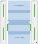
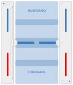
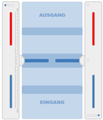
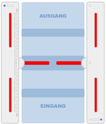
Je nach Aktion werden die nachfolgenden Zustände grafisch in der AnsichtDepending on the action, the following states are displayed graphically in the view ('''<nowiki>http://192.168.1.100/dashboard</nowiki>''') dargestellt.
{{Mehrere Bilder
| Kopfzeile = Zustand normal, Service Eingang, Service, Ausgang, Sperre Eingang, Sperre Ausgang, Sperre beide Richtungen (von links nach rechts)
| align = center
| Breite = 150
| Hintergrund = #EDEDED
| Bild1 = normal.png
| Untertitel1 = normal
| Bild2 = service eingang.png
| Untertitel2 = Service Eingang
| Bild3 = service ausgang.png
| Untertitel3 = Service Ausgang
| Bild4 = sperre eingang.png
| Untertitel4 = Sperre Eingang
| Bild5 = sperre ausgang.png
| Untertitel5 = Sperre Ausgang
| Bild6 = sperre total.png
| Untertitel6 = Sperre beide Richtungen
}}
===Prüfung Lichtleiste===
Die Lichtleiste des Herstellers Duometrics muss zunächst mit dem richtigen Modus kalibriert werden. Die Details können der Anleitung der Hardware entnommen werden. Nach Abschluss der Kalibrierung muss das Anschlussboard diese Einstellungen aufweisen.
{{Multiple images
| Kopfzeile = State normal, service entrance, service, exit, lock entrance, lock exit, lock both directions (from left to right)
| align = center
| Width = 150
| Background = #EDEDED
| Image1 = normal.png
| Subtitle1 = normal
| Image2 = service eingang.png
| Subtitle2 = Service Entry
| Image3 = service ausgang.png
| Subtitle3 = Service Exit
| Image4 = sperre eingang.png
| Subtitle4 = Block Entry
| Image5 = sperre ausgang.png
| Subtitle5 = Block Exit
| Image6 = sperre total.png
| Subtitle6 = Block both directions
}}
===Test Lightbar===
The light bar from the manufacturer Duometrics must first be calibrated with the correct mode. The details can be found in the hardware instructions. After the calibration is complete, the connector board must have these settings.
[[Datei:DuoMetrics Settings.jpg|ohne|mini]]
Die korrekte Konfiguration der Lichtleiste kann auf der Statusseite The correct configuration of the light bar can be checked on the status page ('''<nowiki>http://192.168.1.100/status</nowiki>''') der Anwendung geprüft werden.
of the application.
[[Datei:image status lightbar.png|ohne|mini]]
Wenn ein Fehler in der Kommunikation auftritt, wird dieser Fehler hier entsprechend angezeigtIf an error occurs in the communication, this error is displayed here accordingly.
[[Datei:Gate Lichtleiste Status erroe.png|ohne|mini]]
Nachdem die Einstellungen geprüft worden sind, kann man die Funktion testen, indem in Eingangsrichtung der Zustand "Dauerfrei" eingestellt wird. Dies geschieht über die Konfiguration des Barcodelesegerätes After the settings have been checked, the function can be tested by setting the "Permanently free" status in the entry direction. This is done via the configuration of the barcode reader ('''<nowiki>http://192.168.1.100/configuration#barcode_scanner_entry</nowiki>'''). Dort wird der Eintrag "Light Bar" ausgewähltThere the entry "Light Bar" is selected.
[[Datei:Gate Dauerfrei Eingang.png|ohne|mini]]
Danach kann eine Person in Eingangsrichtung das Gate durchschreiten. Auf dem Dashboard wird diese Aktion visuell dargestelltAfter that, one person can walk through the gate in the direction of entry. This action is represented visually on the dashboard.
[[Datei:Gate Lichtleiste Check.png|ohne|mini]]
Damit ist die Prüfung der Lichtleiste abgeschlossen.
===Prüfung Lichtband===
Das Lichtband wird mit der Komponente This completes the check of the light bar.
===Test Lightband===
The light band is controlled with the [https://www.diamex.de/dxshop/index.php Diamex] gesteuert. Den Status der Erreichbarkeit dieser Komponente kann man auf der Seite component. The availability status of this component can be displayed on the page. ('''<nowiki>http://192.168.1.100/update</nowiki>''') dargestellt.
[[Datei:Gate Diamex update.png|ohne|mini]]
Dieser Status wird nur nach Konfiguration des Lichtbandes für Master und Slave korrekt dargestellt.
Man muss die aktuellen Motive für die Lichtsteuerung auf das Modul laden. Die Datei befindet sich hierThis status is only displayed correctly after configuration of the light band for master and slave.
You have to load the current motifs for the light control onto the module. The file is located here:
[[:Datei:fmcu-1.3.0.lbo.zip|Lichtbandmotive]]
Der Status der Komponente kann wie bei allen anderen Komponenten auf der Statusseite As with all other components, the status of the component can be checked on the status page. ('''<nowiki>http://192.168.1.100/status</nowiki>''') geprüft werden.
[[Datei:Gate Diamex Check.png|ohne|mini]]
Es gilt zu beachten das es zwei Komponenten für die Lichtbandsteuerung gibt. Für jeden Rahmen sind unterschiedliche Konfigurationsparameter zu berücksichtigen. Es werden grundsätzlich Master und Slave definiert.
{{Mehrere Bilder
| Kopfzeile = Konfiguration Lichtband Master und Slave
| RichtungIt should be noted that there are two components for the light line control. Each frame has different configuration parameters to consider. Master and slave are always defined.
{{Multiple images
| Headline = Configuration lightband master and slave
| Direction = vertical
| align = left
| center = 1
| BreiteWidth = 400
| HintergrundBackground = #EDEDED
| Bild1Image1 = Gate Diamex Master1.png
| Untertitel1Subtitle1 = Lichtband Master
| Bild2Image2 = Gate Diamex Slave.png
| Untertitel2 = LichtbandSubtitle2 = Lightband Slave
}}
{{Box_Hinweis|Hinweis Text = Bei der Konfiguration der Adresse für die Komponente Diamex gilt es zu beachten, dass dort andere Angaben für die USB-Schnittstelle vorzunehmen sind. Es wird hier die Zeichenkette '''/dev/ttyACM0''' eingegeben.}}
Wenn keine LED-Matrix vorhanden ist, sollte "No matrix" Hint|text = When configuring the address for the Diamex component, it is important to note that other specifications for the USB interface must be made there. The character string is entered here. '''/dev/ttyACM0'''}}
If there is no LED matrix, "No matrix" should be activated.('''<nowiki>https://192.168.1.100/configuration#led_player_master</nowiki>''') aktiviert werden.
[[Datei:fmcu nomatrix.png|ohne|mini]]
Das Lichtband muss auf beiden Rahmenhälften ein synchrones Verhalten aufweisen. Darum wird auf der Masterseite die Kommunikation mit der Slaveseite eingestellt.
DarstellungThe light band must behave synchronously on both halves of the frame. For this reason, communication with the slave side is set on the master side.
Display Master FMCU ('''<nowiki>http://192.168.1.101/api</nowiki>''')
[[Datei:Config LED Player Slave am Master.png|ohne|mini]]
==Funktionstests==
==Einrichten der Anlage beim Kunden==
Beim Aufbau der Anlage im Kundennetzwerk muss zunächst die Netzwerkkonfiguration angepasst werden. Dazu meldet man sich mit wie bereits bei der Inbetriebnahme über den Web-Browser mit den hinterlegten Anmeldeinformationen an, nachdem der Computer über das Netzwerk mit der Zutrittskontrolle verbunden worden ist.
Jetzt wechselt man auf die Seite System Functional Tests==
==Setting up the System at the Customer==
When setting up the system in the customer network, the network configuration must first be adjusted. To do this, you log in with the web browser with the stored login information, as you did during commissioning, after the computer has been connected to the access control system via the network.
Now go to the System page and select the ''Network'' tab there. ('''<nowiki>http://192.168.1.100/system</nowiki>''') und wählt dort den Reiter ''Netzwerk'' aus.
[[Datei:image gate network1.png|ohne|mini]]
Hier trägt man die vom Kunden bereitgestellten Netzwerk-Informationen für IP-Adresse, Netzmaske, Gateway und DNS-Server ein, klickt auf ''Speichern'' und startet das System (''System neu starten'') neu. Danach wird das Netzwerkkabel des Kundennetzwerkes mit der Anlage verbunden und die weiteren Einstellungen können mit jedem PC im Kundennetzwerk fortgesetzt werden.
==Softwarebausteine==
Die Benutzeroberfläche unterstützt die Konfiguration der Zutrittskontrolle durch standardisierte Abläufe, die in Form so genannter Softwarebausteine zusammengefasst werden. Die einzelnen Einstellungsmöglichkeiten werden nachfolgend aufgeführt. Die verschiedenen Einstellungen werden in Kategorien gebündelt und orientieren sich an ähnlichen Bewegungsabläufen.
===Standard I (horizontale LichtleisteHere you enter the network information provided by the customer for IP address, net mask, gateway and DNS server, click on ''Save'' and restart the system (''Restart system''). Then the network cable of the customer network is connected to the system and the other settings can be continued with any PC in the customer network.
==Software Building Blocks==
The user interface supports the configuration of the access control through standardized processes that are summarized in the form of so-called software modules. The individual setting options are listed below. The various settings are bundled into categories and are based on similar movement sequences.
===Standard I (horizontal lightbar)===
[[Datei:software settings.png|ohne|mini]]
{| class="wikitable"
|+
!Funktion
!BeschreibungFunction
!Description
!Standard
|-
|Tailgating Eingang
|Die Zutrittskontrolle ist für den Einzeldurchgang konfiguriert. Die Prüfung des Durchgangs erfolgt durch Präsentieren des Tickets am Kartenleser. Wenn nach dem Durchgang einer erfolgreichen Prüfung eine zweite Person ohne Prüfung den Durchgang nutzt, wird ein Alarm mit visuellem und akustischem Alarm ausgelöst. Die Zutrittskontrolle kann entweder wie folgt reagieren. Es wird sofort der Schließvorgang gestartet ohne Berücksichtigung von Personen im Schwenkbereich. Der Schließvorgang startet nur dann, wenn sich keine Person im Schwenkbereich befindet.
Folgende Optionen ergeben sich daraus:
- kein Alarm
- Alarm
- Alarm und Schließen nach Verlassen des Schwenkbereich
- Alarm und sofort Schließen
|kein Alarm
|-
|Tailgating Ausgang
|Die Beschreibung ist analog der Funktion "Tailgating Eingang"
|kein Alarm
|-
|Lichtleiste wird zum Erkennen des Tailgating verwendet
|Wenn dieser Schalter aktiviert ist, wird die Lichtleiste für die Personenerkennung verwendet.
|aktiviert
|-
|Deckensensor wird zum Erkennen des Tailgating verwendet
|Wenn dieser Schalter aktiviert ist, wird der Deckensensor für die Personenerkennung verwendet.
|nicht aktiviert
|-
|Tailgating in dem ganzen Durchgang erkennen
|Diese Funktion kann nur bei Verwendung des Deckensensors genutzt werden. Die Fläche vor dem Glasbügel ist in zwei Zonen eingeteilt. Es gibt eine "Outerzone" und eine "Innerzone". Wenn diese Funktion aktiviert ist, wird die 2. Person bereits in der "Outerzone" erkannt. Der Alarm kann also zu einem früheren Zeitpunkt erfolgen.
|nicht aktiviert
|-
|Gegenlauf
|Bei Verwendung der Lichtleiste erfolgt die Identifizierung mit dem Eintritt in den Rahmen. Bei Verwendung der Kamera kann dieser Effekt bereits vor Eintritt des Rahmens entdeckt werden. Es sind folgende Optionen möglich:
- kein Alarm
- Alarm
- Alarm und Schließen nach Verlassen des Schwenkbereich
- Alarm und sofort Schließen
|kein Alarm
|-
|Lichtleiste wird zum Erkennen des Gegenlauf verwendet
|Wenn dieser Schalter aktiviert ist, wird die Lichtleiste als Sensor verwendet.
|aktiviert
|-
|Deckensensor wird zum Erkennen des Gegenlauf verwendet
|Wenn dieser Schalter aktiviert ist, wird der Deckensensor als Sensor verwendet.
|nicht aktiviert
|-
|Gegenlauf in dem ganzen Durchgang erkennen
|Diese Funktion kann nur bei Verwendung des Deckensensors genutzt werden. Die Fläche vor dem Glasbügel ist in zwei Zonen eingeteilt. Es gibt eine "Outerzone" und eine "Innerzone". Wenn diese Funktion aktiviert ist, wird die 2. Person bereits in der "Outerzone" erkannt. Der Alarm kann also zu einem früheren Zeitpunkt erfolgen.
|nicht aktiviert
|}
===Standard II (vertikale Lichtleiste und horizontale LichtleisteEntry
|Access control is configured for single pass. The passage is checked by presenting the ticket at the card reader. If, after passing a successful test, a second person uses the passage without a test, an alarm with visual and audible alarm is triggered. The access control can either react as follows. The closing process is started immediately, regardless of people in the pivoting area. The closing process only starts when nobody is in the pivoting area.
This results in the following options:
- no Alarm
- Alarm
- Alarm and closing after leaving the swivel range
- Alarm and close immediately
|no Alarm
|-
|Tailgating Exit
|The description is analogous to the "Tailgating input" function
|no Alarm
|-
|Light bar is used to detect Tailgating
|If this switch is activated, the light bar is used for person detection.
|activated
|-
|Ceiling sensor is used to detect tailgating
|If this switch is activated, the ceiling sensor is used for people detection.
|not activated
|-
|Detect tailgating throughout the run
|This function can only be used when using the ceiling sensor. The area in front of the glass bracket is divided into two zones. There is an "outer zone" and an "inner zone". If this function is activated, the 2nd person is already recognized in the "outer zone". The alarm can therefore be given at an earlier point in time.
|not activated
|-
|reverse
|When using the light bar, identification occurs when entering the frame. When using the camera, this effect can be detected before the frame enters. The following options are possible:
- no Alarm
- Alarm
- Alarm and closing after leaving the swivel range
- Alarm and close immediately
|no Alarm
|-
|Light bar is used to detect reverse rotation
|When this switch is activated, the light bar is used as a sensor.
|activated
|-
|Ceiling sensor is used to detect counter-rotation
|If this switch is activated, the ceiling sensor is used as a sensor.
|not activated
|-
|Detect reverse flow throughout the passage
|This function can only be used when using the ceiling sensor. The area in front of the glass bracket is divided into two zones. There is an "outer zone" and an "inner zone". If this function is activated, the 2nd person is already recognized in the "outer zone". The alarm can therefore be given at an earlier point in time.
|not activated
|}
===Standard II (vertical light bar and horizontal light bar)===
[[Datei:software settings 01.png|ohne|mini]]
{| class="wikitable"
|+
!Funktion
!BeschreibungFunction
!Description
!Standard
|-
|Höhendefinition bei eintretenden Objekten (insbesondere Kinder)
|
|
|-
|
|
|
|-
|
|
|
|}
===Premium (horizontale und vertikale Lichtleiste inkl. 1 DeckensensorHeight definition for entering objects (especially children)
|
|
|-
|
|
|
|-
|
|
|
|}
===Premium (horizontal and vertical light bar inkl. 1 Ceiling Sensor)===
[[Datei:software settings 03.png|ohne|mini]]
{| class="wikitable"
|+
!Funktion
!BeschreibungFunction
!Description
!Standard
|-
|Höhendefinition bei eintretenden Objekten (insbesondere Kinder). Person darf mit Trolley das Gate passieren. Anschließend schließen die Schwenkarme nach verlassen des Schwenkbereichs
|
|
|-
|Erweitertes Tailgating durch Deckensensor (kein Einfluss auf Benutzeroberfläche)
|
|
|-
|
|
|
|}
===Erweitertes Tailgating durch Deckensensor (kein Einfluss auf BenutzeroberflächeHeight definition for entering objects (especially children). person may pass through the gate with a trolley. The swivel arms then close after leaving the swivel range
|
|
|-
|Extended tailgating by ceiling sensor (no influence on user interface)
|
|
|-
|
|
|
|}
===Extended Tailgating by ceiling Sensor (no influence on user interface)===
[[Datei:software settings 04.png|ohne|mini]]
{| class="wikitable"
|+
!Funktion
!BeschreibungFunction
!Description
!Standard
|-
|Einzelerkennung am Kartenleser, die Lesebereiche dürfen immer nur Einzel betreten werden, ansonsten öffnet das Gate nicht. Bei Manipulationsversuch schließt das Gate in jedem Fall.
|
|
|-
|zus. Überwachung von Flächen im Umfeld der Zutrittskontrolle
|
|
|-
|
|
|
|}
===ZusatzoptionenIndividual recognition on the card reader, the reading areas may only be entered individually, otherwise the gate will not open. In the event of an attempt at manipulation, the gate closes in any case.
|
|
|-
|additional monitoring of areas in the vicinity of the access control
|
|
|-
|
|
|
|}
===Additional Options===
[[Datei:software settings 05.png|ohne|mini]]
{| class="wikitable"
|+
!Funktion
!BeschreibungFunction
!Description
!Standard
|-
|PfeilArrow-X-Signalisierung Eingang
|
|
|-
|Pfeil-X-Signalisierung Ausgang
|
|
|-
|Lichtband Master
|
|
|-
|Lichtband Slave
|
|
|-
|Lautsprecher
|
|
|}<br />
===Audiodateien===
Die Zuordnung der MP3-Datei-Namen zur Verwendung kann der folgenden Tabelle entnommen werden:
{| class="wikitable"
|+
!Name
!FunktionSignal Entry
|
|
|-
|Arrow-X Signal Exit
|
|
|-
|Lightband Master
|
|
|-
|Lightband Slave
|
|
|-
|Speaker
|
|
|}<br />
===Audio-Files===
The assignment of the MP3 file names for use can be found in the following table:
{| class="wikitable"
|+
!Name
!Function
|-
|MP3_1.mp3
|Beep nachdem einafter a Barcode gelesen worden isthas been read
|-
|MP3_2.mp3
|Bitte gehen Sie durch das Please go through the Gate
|-
|MP3_3.mp3
|Zufälliger TrefferRandom Hit
|-
|MP3_4.mp3
|Alarm
|-
|MP3_5.mp3
|Den Leserbereich bitte einzeln betreten
|-
|MP3_6.mp3
|Bitte verlassen Sie den Leserbereich
|-
|MP3_7.mp3
|NotaufPlease enter the readers' area individually
|-
|MP3_6.mp3
|Please leave the readers area
|-
|MP3_7.mp3
|Emergency
|}
{{Links
| Thema1 = [[Gate_~_FMCU_Galaxy_Gate_~_user_manual | Galaxy Gate BedienungsanleitungOperation Manual]]
| Thema2 = [[Gate_~_FMCU_~_management_dashboard | Beschreibung zentralesDescription Central Dashboard]]
}}
[[Kategorie:Galaxy Gate]]
{{DEFAULTSORT:Gate ~ Installation}}
[[Kategorie:Galaxy Gate EN]]| (3 dazwischenliegende Versionen desselben Benutzers werden nicht angezeigt) | |||
| Zeile 11: | Zeile 11: | ||
| − | == | + | ==Preparation== |
| − | + | The commissioning of the Galaxy Gate is started by providing an image. The network configuration is prepared with a static IP address. The external camera XOVIS is also equipped with a static IP address. | |
{| class="wikitable" | {| class="wikitable" | ||
|'''Device''' | |'''Device''' | ||
| Zeile 24: | Zeile 24: | ||
|192.168.1.168 | |192.168.1.168 | ||
|} | |} | ||
| − | + | These initial parameters are part of the image. All further steps are based on this configuration of the IP addresses. | |
| − | {{ | + | {{Hint|text = The network configuration parameters must be verified before the hardware is shipped to the customer to ensure access control is working properly. In addition, the RFID reader components depend on customer requirements. The correct configuration of the '''F'''acility '''M'''anagement '''C'''ontrol '''U'''nit (FMCU) is essential for a successful implementation at the customer.}}The image is provided in the form of a file from maxcrc via a specified download URL. maxcrc updates the image in case of software changes such as bug fixes or the support of new hardware components. It must always be checked in advance whether the current image exists in the download area. Current sources are listed below. |
{| class="wikitable" | {| class="wikitable" | ||
| Zeile 45: | Zeile 45: | ||
| − | + | This file is now extracted and copied to the eMMC card using a software tool. This process can be performed on any Windows computer that has a card reader with a micro SD slot.<br />The image is now transferred to the SD card using the "Win32DiskImager" tool. The tool can be downloaded here: | |
[https://dn.odroid.com/DiskImager_ODROID/ DiskImager_ODROID] | [https://dn.odroid.com/DiskImager_ODROID/ DiskImager_ODROID] | ||
| Zeile 51: | Zeile 51: | ||
<br /> | <br /> | ||
| − | {{ | + | {{Multiple Images |
| − | | | + | | Headline = Tools for transferring the image file to the SD card |
| align = center | | align = center | ||
| − | | | + | | Background = #EDEDED |
| − | | | + | | Image1 = MicroSD Cover.png |
| − | | | + | | Subtitle1 = MicroSD Cover |
| − | | | + | | Width1 = 200 |
| − | | | + | | Image2 = image SD card cover.png |
| − | | | + | | Subtitle2 = SD card |
| − | | | + | | Width2 = 200 |
| − | | | + | | Image3 = image SD card Leser.png |
| − | | | + | | Subtitle3 = SD Card Leser |
| − | | | + | | Width3 = 350 |
}} | }} | ||
| − | <br /> | + | <br />After launching the program, select the previously extracted image file. The device letter is the drive assigned to the SD card on the PC. Make sure the eMMC adapter and eMMC card are properly inserted before clicking the button. You must confirm the writing before the process begins. After writing, you need to click on the "Verify" button to ensure that the written data has been transferred to the eMMC card without errors. <br />{{Mehrere Bilder |
| − | | | + | | Headline = User Interface Image Tool |
| align = center | | align = center | ||
| − | | | + | | Background = #EDEDED |
| − | | | + | | Width = 250 |
| − | | | + | | Image1 = image tool dialog.png |
| − | | | + | | Subtitle1 = Imagetool Dialog |
| − | | | + | | Image2 = image tool confirmation dialog.png |
| − | | | + | | Subtitle2 = Write Confirmation |
| − | | | + | | Image3 = image ODROID SD card cover.png |
| − | | | + | | Subtitle3 = ODROID Card Slot View |
}} | }} | ||
| − | + | The final step is to insert the prepared eMMC card into the ODROID single-board computer. | |
| − | + | Remove the protective film of the double-sided tape: | |
<br /> | <br /> | ||
| Zeile 88: | Zeile 88: | ||
| − | + | Align the eMMC module and the eMMC connector flush on the ODROID-C2 board using the white rectangle on the board as a guide. | |
| − | + | Slowly push in the eMMC until the card clicks into place. | |
| − | <br /> | + | <br />Now the single-board computer is connected to a computer via a network cable. After switching on the power supply of the access control, the configuration can be continued with an Internet browser (e.g. Chrome). |
| − | '''USB- | + | '''USB-Pinout ODROID''' |
[[Datei:USB-ODROID.png|ohne|mini]] | [[Datei:USB-ODROID.png|ohne|mini]] | ||
| − | + | The pin assignment of the single-board computer is shown in the following illustration. | |
{| class="wikitable" | {| class="wikitable" | ||
| − | !''' | + | !'''Connection''' |
| − | !''' | + | !'''Description''' |
|- | |- | ||
|USB1 | |USB1 | ||
| Zeile 107: | Zeile 107: | ||
|- | |- | ||
|USB2 | |USB2 | ||
| − | |RS232-Adapter | + | |RS232-Adapter for DUOmetrics |
|- | |- | ||
|USB3 | |USB3 | ||
| − | |LED-Controller | + | |LED-Controller for LED-Matrix and LED-Lightband |
|- | |- | ||
|USB4 | |USB4 | ||
| − | |USB-RS485 nano Adapter | + | |USB-RS485 nano Adapter for WEAC-Board |
|} | |} | ||
| − | == | + | ==Technical Information== |
| − | === | + | ===Configuration=== |
| − | + | The IP address is entered in the browser's URL bar. '''<nowiki>http://192.168.1.100</nowiki>''' | |
| + | The following login window appears | ||
[[Datei:Anmeldung FMCU.png|ohne|mini]] | [[Datei:Anmeldung FMCU.png|ohne|mini]] | ||
| − | + | The following login information is stored: | |
{| class="wikitable" | {| class="wikitable" | ||
|+ | |+ | ||
| − | ! | + | !Username |
| − | ! | + | !Password |
|- | |- | ||
|wanzl | |wanzl | ||
|wanzlfmcu! | |wanzlfmcu! | ||
|} | |} | ||
| − | + | After successful login, this view appears. | |
[[Datei:Dashboard FMCU de.png|ohne|mini]] | [[Datei:Dashboard FMCU de.png|ohne|mini]] | ||
| − | In | + | In this representation you can already read different information and determine the status of the access control. The left visual representation of the access control describes the current status. If the bracket light is not flashing red, the condition is normal and the connection between FMCU and WEAC has been established successfully. The two LED displays in the horizontal display of unit 1 and unit 2 also indicate the connection status visually. The current version of the WEAC firmware is shown in brackets. |
| − | {{ | + | {{Multiple Images |
| − | | | + | | Headline = #EDEDED |
| − | | | + | | Direction = vertical |
| align = left | | align = left | ||
| center = 1 | | center = 1 | ||
| Breite = 400 | | Breite = 400 | ||
| − | | | + | | Image1 = Gate Status ok.png |
| − | + | | Subtitle1 = WEAC Unit available | |
| − | | | + | | Image2 = Gate Status wrong.png |
| − | | | + | | Subtitle2 = WEAC Unit not available |
| − | | | ||
}} | }} | ||
| − | + | In the event of an error, you must check the address of the USB access. On the system page of the application ('''<nowiki>http://192.168.1.100/system</nowiki>''') all USB ports used are displayed. | |
[[Datei:image system page.png|ohne|mini]] | [[Datei:image system page.png|ohne|mini]] | ||
| − | In | + | In this example, three components are connected. |
{| class="wikitable" | {| class="wikitable" | ||
|+ | |+ | ||
| − | ! | + | !Connection |
| − | ! | + | !Usage |
|- | |- | ||
|/dev/ttyUSB2 | |/dev/ttyUSB2 | ||
| − | | | + | |Components1 |
|- | |- | ||
|/dev/ttyUSB1 | |/dev/ttyUSB1 | ||
| − | | | + | |Components2 |
|- | |- | ||
|/dev/ttyUSB0 | |/dev/ttyUSB0 | ||
| − | | | + | |Components3 |
|} | |} | ||
| − | + | The connection to WEAC is always shown with the USB0 or USB1 connections. You can check the current settings by looking at the configuration of the gate ('''<nowiki>http://192.168.1.100/configuration#gate</nowiki>''') | |
[[Datei:Gate Modbus.png|ohne|mini]] | [[Datei:Gate Modbus.png|ohne|mini]] | ||
| − | + | Setting the address of the USB port to the WEAC board is further down this dialog. "Simulator" is set for Gate on the Slave FMCU. | |
[[Datei:Gate Port.png|ohne|mini]] | [[Datei:Gate Port.png|ohne|mini]] | ||
| − | + | When using a slave FMCU, the IP address is set via the menu ('''<nowiki>http://192.168.1.100/configuration#slave_fmcu</nowiki>'''). | |
[[Datei:slave fmcu.png|ohne|mini]] | [[Datei:slave fmcu.png|ohne|mini]] | ||
| − | + | Furthermore, the IP address must be entered in the white list under "Authentication and linked gates". | |
[[Datei:whitelist.png|ohne|mini]] | [[Datei:whitelist.png|ohne|mini]] | ||
Master-FMCU: 192.168.1.101, Slave-FMCU: 192.168.1.100 | Master-FMCU: 192.168.1.101, Slave-FMCU: 192.168.1.100 | ||
| − | + | When using the light bar, it is also important to ensure that all three sensors are activated. | |
[[Datei:Gate Lichtleiste Sensoren.png|ohne|mini]] | [[Datei:Gate Lichtleiste Sensoren.png|ohne|mini]] | ||
| − | + | The parameters of the light bar are set via the menu navigation ('''<nowiki>http://192.168.1.100/configuration#light_bar</nowiki>'''). | |
[[Datei:Lichtleiste Parameter.png|ohne|mini]] | [[Datei:Lichtleiste Parameter.png|ohne|mini]] | ||
| − | + | The values listed here can be accepted as standard. Before the light bar can be used, a self-adjustment must be carried out. These steps are explained below. | |
| − | 1. | + | 1. There is no supply voltage at the light bar controller. The device is switched off. |
| − | 2. | + | 2. Monitoring area is free. |
| − | 3. DIP3 | + | 3. DIP3 to ON (Evaluation on LVX board) |
| − | 4. | + | 4. turn on a device. |
[[Datei:LED DUOMetrics.png|mini]] | [[Datei:LED DUOMetrics.png|mini]] | ||
| − | 5. LEDs ''' | + | 5. LEDs '''check''': |
| − | + | The green LED D should light up. (evaluation on LVX board) <sub> </sub> | |
| − | + | No blinking or glowing of the red error LEDs. | |
| − | 6. DIP3 | + | 6. DIP3 back to OFF during operation. |
| − | => | + | => The device saves the values in the EEPROM and goes into normal operation. If you do not want to save the setting: Switch off the supply as long as DIP3 is ON. |
| − | ''' | + | '''Notice:''' |
| − | + | If the device is switched off while the reference values are being saved (before LED "B" flashes), this can lead to unintentional blanking. | |
| − | LED | + | LED states during self-adjustment |
{| class="wikitable" | {| class="wikitable" | ||
| colspan="2" | | | colspan="2" | | ||
| Zeile 218: | Zeile 218: | ||
|'''LED E''' | |'''LED E''' | ||
|'''LED Rx,Tx''' | |'''LED Rx,Tx''' | ||
| − | |''' | + | |'''comment''' |
|- | |- | ||
| | | | ||
| Zeile 225: | Zeile 225: | ||
| − | + | On | |
<br /> | <br /> | ||
| | | | ||
| − | + | Off | |
| | | | ||
| − | + | Off | |
| | | | ||
| − | + | self-alignment o.k. | |
|- | |- | ||
| colspan="2" | | | colspan="2" | | ||
| Zeile 241: | Zeile 241: | ||
| − | + | Off | |
| rowspan="3" | | | rowspan="3" | | ||
| Zeile 247: | Zeile 247: | ||
| − | + | On | |
| rowspan="3" | | | rowspan="3" | | ||
| Zeile 253: | Zeile 253: | ||
| − | + | Off | |
| − | | rowspan="3" | | + | | rowspan="3" |Can be accepted Possible causes: |
| − | • | + | • Too great distance between transmitter and |
| − | + | recipient | |
| − | => | + | => reduce distance; Use transmitter bars with the "increased transmitter power" option. |
| − | • | + | • Individual beams covered or dirty. |
| − | • | + | • The difference in brightness between the strongest and weakest rays is too great. |
|- | |- | ||
| rowspan="2" | | | rowspan="2" | | ||
| Zeile 274: | Zeile 274: | ||
| | | | ||
| | | | ||
| − | | | + | |On or blink |
| − | | | + | |Self-alignment '''failed'''! |
| − | + | Individual beams are recognized as defective. | |
| − | + | Only emergency operation is possible! | |
|} | |} | ||
| − | + | After all settings have been checked and adjusted if necessary, you can carry out various actions on the dashboard page. | |
[[Datei:image action buttons.png|ohne|mini]] | [[Datei:image action buttons.png|ohne|mini]] | ||
| − | + | Depending on the action, the following states are displayed graphically in the view ('''<nowiki>http://192.168.1.100/dashboard</nowiki>'''). | |
| − | {{ | + | {{Multiple images |
| − | | Kopfzeile = | + | | Kopfzeile = State normal, service entrance, service, exit, lock entrance, lock exit, lock both directions (from left to right) |
| align = center | | align = center | ||
| − | | | + | | Width = 150 |
| − | | | + | | Background = #EDEDED |
| − | | | + | | Image1 = normal.png |
| − | | | + | | Subtitle1 = normal |
| − | | | + | | Image2 = service eingang.png |
| − | | | + | | Subtitle2 = Service Entry |
| − | | | + | | Image3 = service ausgang.png |
| − | | | + | | Subtitle3 = Service Exit |
| − | | | + | | Image4 = sperre eingang.png |
| − | | | + | | Subtitle4 = Block Entry |
| − | | | + | | Image5 = sperre ausgang.png |
| − | | | + | | Subtitle5 = Block Exit |
| − | | | + | | Image6 = sperre total.png |
| − | | | + | | Subtitle6 = Block both directions |
}} | }} | ||
| − | === | + | ===Test Lightbar=== |
| − | + | The light bar from the manufacturer Duometrics must first be calibrated with the correct mode. The details can be found in the hardware instructions. After the calibration is complete, the connector board must have these settings. | |
[[Datei:DuoMetrics Settings.jpg|ohne|mini]] | [[Datei:DuoMetrics Settings.jpg|ohne|mini]] | ||
| − | + | The correct configuration of the light bar can be checked on the status page ('''<nowiki>http://192.168.1.100/status</nowiki>''') of the application. | |
[[Datei:image status lightbar.png|ohne|mini]] | [[Datei:image status lightbar.png|ohne|mini]] | ||
| − | + | If an error occurs in the communication, this error is displayed here accordingly. | |
[[Datei:Gate Lichtleiste Status erroe.png|ohne|mini]] | [[Datei:Gate Lichtleiste Status erroe.png|ohne|mini]] | ||
| − | + | After the settings have been checked, the function can be tested by setting the "Permanently free" status in the entry direction. This is done via the configuration of the barcode reader ('''<nowiki>http://192.168.1.100/configuration#barcode_scanner_entry</nowiki>'''). There the entry "Light Bar" is selected. | |
[[Datei:Gate Dauerfrei Eingang.png|ohne|mini]] | [[Datei:Gate Dauerfrei Eingang.png|ohne|mini]] | ||
| − | + | After that, one person can walk through the gate in the direction of entry. This action is represented visually on the dashboard. | |
[[Datei:Gate Lichtleiste Check.png|ohne|mini]] | [[Datei:Gate Lichtleiste Check.png|ohne|mini]] | ||
| − | + | This completes the check of the light bar. | |
| − | === | + | ===Test Lightband=== |
| − | + | The light band is controlled with the [https://www.diamex.de/dxshop/index.php Diamex] component. The availability status of this component can be displayed on the page. ('''<nowiki>http://192.168.1.100/update</nowiki>'''). | |
[[Datei:Gate Diamex update.png|ohne|mini]] | [[Datei:Gate Diamex update.png|ohne|mini]] | ||
| − | + | This status is only displayed correctly after configuration of the light band for master and slave. | |
| − | + | You have to load the current motifs for the light control onto the module. The file is located here: | |
[[:Datei:fmcu-1.3.0.lbo.zip|Lichtbandmotive]] | [[:Datei:fmcu-1.3.0.lbo.zip|Lichtbandmotive]] | ||
| − | + | As with all other components, the status of the component can be checked on the status page. ('''<nowiki>http://192.168.1.100/status</nowiki>'''). | |
[[Datei:Gate Diamex Check.png|ohne|mini]] | [[Datei:Gate Diamex Check.png|ohne|mini]] | ||
| − | + | It should be noted that there are two components for the light line control. Each frame has different configuration parameters to consider. Master and slave are always defined. | |
| − | {{ | + | {{Multiple images |
| − | | | + | | Headline = Configuration lightband master and slave |
| − | | | + | | Direction = vertical |
| align = left | | align = left | ||
| center = 1 | | center = 1 | ||
| − | | | + | | Width = 400 |
| − | | | + | | Background = #EDEDED |
| − | | | + | | Image1 = Gate Diamex Master1.png |
| − | | | + | | Subtitle1 = Lichtband Master |
| − | | | + | | Image2 = Gate Diamex Slave.png |
| − | | | + | | Subtitle2 = Lightband Slave |
}} | }} | ||
| − | {{ | + | {{Hint|text = When configuring the address for the Diamex component, it is important to note that other specifications for the USB interface must be made there. The character string is entered here. '''/dev/ttyACM0'''}} |
| − | + | If there is no LED matrix, "No matrix" should be activated.('''<nowiki>https://192.168.1.100/configuration#led_player_master</nowiki>''') | |
[[Datei:fmcu nomatrix.png|ohne|mini]] | [[Datei:fmcu nomatrix.png|ohne|mini]] | ||
| − | + | The light band must behave synchronously on both halves of the frame. For this reason, communication with the slave side is set on the master side. | |
| − | + | Display Master FMCU ('''<nowiki>http://192.168.1.101/api</nowiki>''') | |
[[Datei:Config LED Player Slave am Master.png|ohne|mini]] | [[Datei:Config LED Player Slave am Master.png|ohne|mini]] | ||
| − | == | + | ==Functional Tests== |
| − | == | + | ==Setting up the System at the Customer== |
| − | + | When setting up the system in the customer network, the network configuration must first be adjusted. To do this, you log in with the web browser with the stored login information, as you did during commissioning, after the computer has been connected to the access control system via the network. | |
| − | + | Now go to the System page and select the ''Network'' tab there. ('''<nowiki>http://192.168.1.100/system</nowiki>''') | |
[[Datei:image gate network1.png|ohne|mini]] | [[Datei:image gate network1.png|ohne|mini]] | ||
| − | + | Here you enter the network information provided by the customer for IP address, net mask, gateway and DNS server, click on ''Save'' and restart the system (''Restart system''). Then the network cable of the customer network is connected to the system and the other settings can be continued with any PC in the customer network. | |
| − | == | + | ==Software Building Blocks== |
| − | + | The user interface supports the configuration of the access control through standardized processes that are summarized in the form of so-called software modules. The individual setting options are listed below. The various settings are bundled into categories and are based on similar movement sequences. | |
| − | ===Standard I ( | + | ===Standard I (horizontal lightbar)=== |
[[Datei:software settings.png|ohne|mini]] | [[Datei:software settings.png|ohne|mini]] | ||
{| class="wikitable" | {| class="wikitable" | ||
|+ | |+ | ||
| − | ! | + | !Function |
| − | ! | + | !Description |
!Standard | !Standard | ||
|- | |- | ||
| − | |Tailgating | + | |Tailgating Entry |
| − | | | + | |Access control is configured for single pass. The passage is checked by presenting the ticket at the card reader. If, after passing a successful test, a second person uses the passage without a test, an alarm with visual and audible alarm is triggered. The access control can either react as follows. The closing process is started immediately, regardless of people in the pivoting area. The closing process only starts when nobody is in the pivoting area. |
| − | + | This results in the following options: | |
| − | - | + | - no Alarm |
- Alarm | - Alarm | ||
| − | - Alarm | + | - Alarm and closing after leaving the swivel range |
| − | - Alarm | + | - Alarm and close immediately |
| − | | | + | |no Alarm |
|- | |- | ||
| − | |Tailgating | + | |Tailgating Exit |
| − | | | + | |The description is analogous to the "Tailgating input" function |
| − | | | + | |no Alarm |
|- | |- | ||
| − | | | + | |Light bar is used to detect Tailgating |
| − | | | + | |If this switch is activated, the light bar is used for person detection. |
| − | | | + | |activated |
|- | |- | ||
| − | | | + | |Ceiling sensor is used to detect tailgating |
| − | | | + | |If this switch is activated, the ceiling sensor is used for people detection. |
| − | | | + | |not activated |
|- | |- | ||
| − | | | + | |Detect tailgating throughout the run |
| − | | | + | |This function can only be used when using the ceiling sensor. The area in front of the glass bracket is divided into two zones. There is an "outer zone" and an "inner zone". If this function is activated, the 2nd person is already recognized in the "outer zone". The alarm can therefore be given at an earlier point in time. |
| − | | | + | |not activated |
|- | |- | ||
| − | | | + | |reverse |
| − | | | + | |When using the light bar, identification occurs when entering the frame. When using the camera, this effect can be detected before the frame enters. The following options are possible: |
| − | - | + | - no Alarm |
- Alarm | - Alarm | ||
| − | - Alarm | + | - Alarm and closing after leaving the swivel range |
| − | - Alarm | + | - Alarm and close immediately |
| − | | | + | |no Alarm |
|- | |- | ||
| − | | | + | |Light bar is used to detect reverse rotation |
| − | | | + | |When this switch is activated, the light bar is used as a sensor. |
| − | | | + | |activated |
|- | |- | ||
| − | | | + | |Ceiling sensor is used to detect counter-rotation |
| − | | | + | |If this switch is activated, the ceiling sensor is used as a sensor. |
| − | | | + | |not activated |
|- | |- | ||
| − | | | + | |Detect reverse flow throughout the passage |
| − | | | + | |This function can only be used when using the ceiling sensor. The area in front of the glass bracket is divided into two zones. There is an "outer zone" and an "inner zone". If this function is activated, the 2nd person is already recognized in the "outer zone". The alarm can therefore be given at an earlier point in time. |
| − | | | + | |not activated |
|} | |} | ||
| − | ===Standard II ( | + | ===Standard II (vertical light bar and horizontal light bar)=== |
[[Datei:software settings 01.png|ohne|mini]] | [[Datei:software settings 01.png|ohne|mini]] | ||
{| class="wikitable" | {| class="wikitable" | ||
|+ | |+ | ||
| − | ! | + | !Function |
| − | ! | + | !Description |
!Standard | !Standard | ||
|- | |- | ||
| − | | | + | |Height definition for entering objects (especially children) |
| | | | ||
| | | | ||
| Zeile 457: | Zeile 457: | ||
|} | |} | ||
| − | ===Premium ( | + | ===Premium (horizontal and vertical light bar inkl. 1 Ceiling Sensor)=== |
[[Datei:software settings 03.png|ohne|mini]] | [[Datei:software settings 03.png|ohne|mini]] | ||
{| class="wikitable" | {| class="wikitable" | ||
|+ | |+ | ||
| − | ! | + | !Function |
| − | ! | + | !Description |
!Standard | !Standard | ||
|- | |- | ||
| − | | | + | |Height definition for entering objects (especially children). person may pass through the gate with a trolley. The swivel arms then close after leaving the swivel range |
| | | | ||
| | | | ||
|- | |- | ||
| − | | | + | |Extended tailgating by ceiling sensor (no influence on user interface) |
| | | | ||
| | | | ||
| Zeile 479: | Zeile 479: | ||
|} | |} | ||
| − | === | + | ===Extended Tailgating by ceiling Sensor (no influence on user interface)=== |
[[Datei:software settings 04.png|ohne|mini]] | [[Datei:software settings 04.png|ohne|mini]] | ||
{| class="wikitable" | {| class="wikitable" | ||
|+ | |+ | ||
| − | ! | + | !Function |
| − | ! | + | !Description |
!Standard | !Standard | ||
|- | |- | ||
| − | | | + | |Individual recognition on the card reader, the reading areas may only be entered individually, otherwise the gate will not open. In the event of an attempt at manipulation, the gate closes in any case. |
| | | | ||
| | | | ||
|- | |- | ||
| − | | | + | |additional monitoring of areas in the vicinity of the access control |
| | | | ||
| | | | ||
| Zeile 500: | Zeile 500: | ||
|} | |} | ||
| − | === | + | ===Additional Options=== |
[[Datei:software settings 05.png|ohne|mini]] | [[Datei:software settings 05.png|ohne|mini]] | ||
{| class="wikitable" | {| class="wikitable" | ||
|+ | |+ | ||
| − | ! | + | !Function |
| − | ! | + | !Description |
!Standard | !Standard | ||
|- | |- | ||
| − | | | + | |Arrow-X-Signal Entry |
| | | | ||
| | | | ||
|- | |- | ||
| − | | | + | |Arrow-X Signal Exit |
| | | | ||
| | | | ||
|- | |- | ||
| − | | | + | |Lightband Master |
| | | | ||
| | | | ||
|- | |- | ||
| − | | | + | |Lightband Slave |
| | | | ||
| | | | ||
|- | |- | ||
| − | | | + | |Speaker |
| | | | ||
| | | | ||
|}<br /> | |}<br /> | ||
| − | === | + | ===Audio-Files=== |
| − | + | The assignment of the MP3 file names for use can be found in the following table: | |
{| class="wikitable" | {| class="wikitable" | ||
|+ | |+ | ||
!Name | !Name | ||
| − | ! | + | !Function |
|- | |- | ||
|MP3_1.mp3 | |MP3_1.mp3 | ||
| − | |Beep | + | |Beep after a Barcode has been read |
|- | |- | ||
|MP3_2.mp3 | |MP3_2.mp3 | ||
| − | | | + | |Please go through the Gate |
|- | |- | ||
|MP3_3.mp3 | |MP3_3.mp3 | ||
| − | | | + | |Random Hit |
|- | |- | ||
|MP3_4.mp3 | |MP3_4.mp3 | ||
| Zeile 550: | Zeile 550: | ||
|- | |- | ||
|MP3_5.mp3 | |MP3_5.mp3 | ||
| − | | | + | |Please enter the readers' area individually |
|- | |- | ||
|MP3_6.mp3 | |MP3_6.mp3 | ||
| − | | | + | |Please leave the readers area |
|- | |- | ||
|MP3_7.mp3 | |MP3_7.mp3 | ||
| − | | | + | |Emergency |
|} | |} | ||
{{Links | {{Links | ||
| − | | Thema1 = [[Gate_~_FMCU_Galaxy_Gate_~_user_manual | Galaxy Gate | + | | Thema1 = [[Gate_~_FMCU_Galaxy_Gate_~_user_manual | Galaxy Gate Operation Manual]] |
| − | | Thema2 = [[Gate_~_FMCU_~_management_dashboard | | + | | Thema2 = [[Gate_~_FMCU_~_management_dashboard | Description Central Dashboard]] |
}} | }} | ||
| − | |||
| − | |||
{{DEFAULTSORT:Gate ~ Installation}} | {{DEFAULTSORT:Gate ~ Installation}} | ||
| + | [[Kategorie:Galaxy Gate EN]] | ||


